Final Project: Modular Light Board
Demo
Part 1: Motivation
[from Week 1]
This idea is inspired by a previous PS70 project (the Scratch robot project), because I really liked the modular blocks. The idea tackles the fact that I'm really lazy and don't like having to get out of bed to turn off a light when I'm going to bed: the best "soft" lighting is often far from the bed. Additionally, I like the idea of being able to change the position of the lights in my room (they are usually lamps) and having a remote control which reflects this flexibility.
This project would involve a small grid of squares corresponding to the rough shape of my room. Small blocks with switches corresponding to lights can be placed on the grid, and the lights will turn on/off based on the switch. The blocks can be rearranged to create different patterns, corresponding to their placement in the room. This would require some kind of modifier on the power source for the lights, so that the lights can be turned on/off based on the switch. As a stretch goal, maybe some (red) blocks could be programmed to turn on automatically at a certain time.
Part 2: Planning
[from Week 5]
3D Model
I spent the most time this week working on my final project model. I learned how to animate joints! And I also learned that I should default to using components more often.
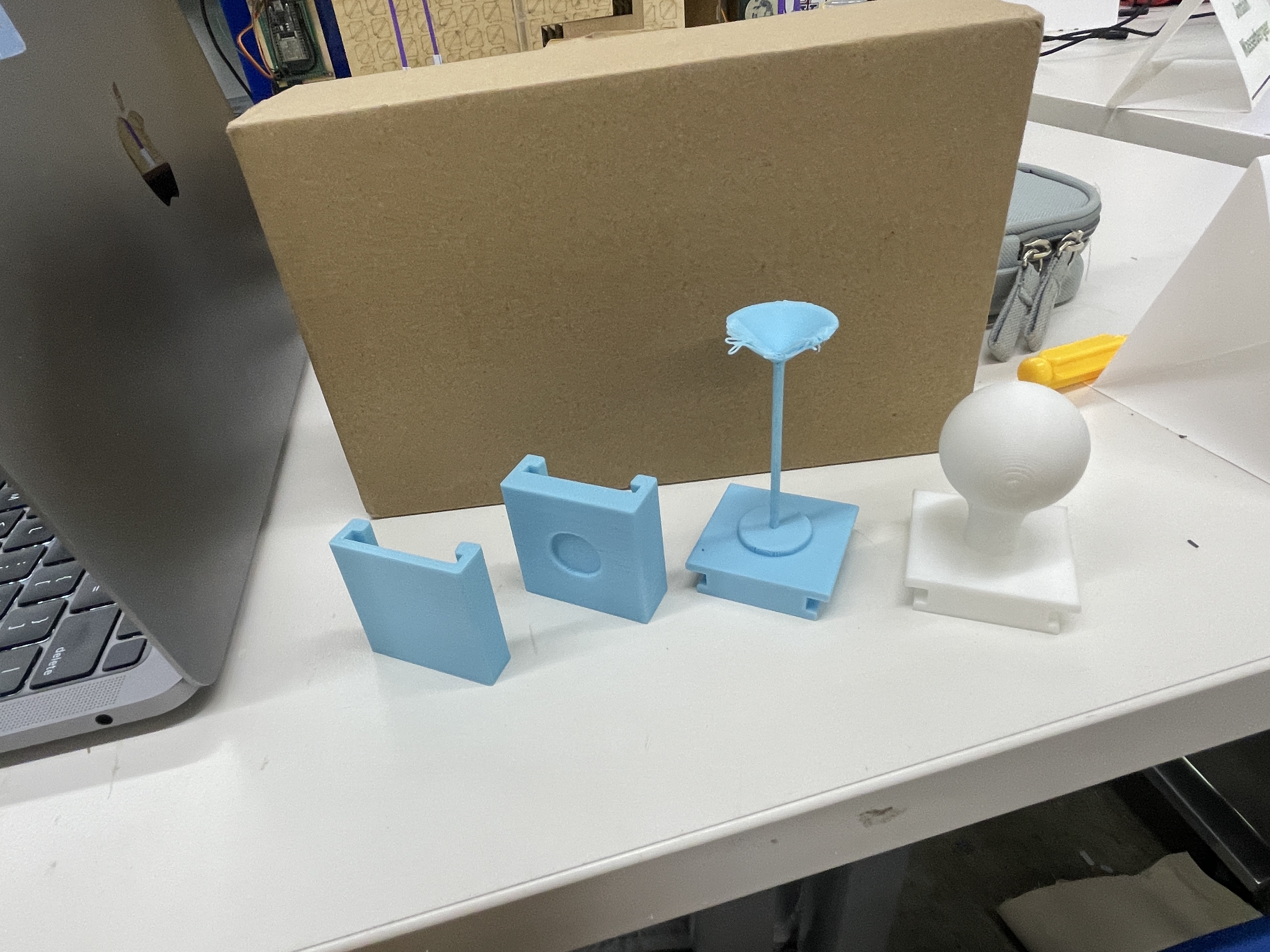
For the main base box, I made little slots for each piece to sit. I also added some height to the box and hollowed it out so that there would be space for circuitry (in case it takes up a lot of space). To ensure access to this, I made the bottom of the box a slide-out drawer. This took forever for me to figure out how to animate, but once I got it, it made it a lot easier to animate the rest of the pieces. I next modeled each of the four pieces to look like little lamps (or a lightbulb).
This model is pretty final, but I have a couple of stretch goals which could slightly alter the design (discussed in the timeline).
Bill of materials
- Wood: The box can be made of wood (since apparently I'm really good at making boxes now)
- 3D print materials: I will likely 3D print each of the pieces
- Magnets: these will be used to complete the circuit whenever a piece is put on the light switch board (Bobby and I ran an experiment to ensure that sautering wires to magnets and then sticking magnets together still allowed current to flow)
- Assorted circuitry: will definitely need a microcontroller which can send RF signals to turn things on/off. I can breadboard this to start, but hopefully want to make this circuit pretty & small.
- 433MHz RF Smart Plug (I think): so I can hack the remote and safely have my arduino control plugged-in devices
Timeline
- By the end of week 6, I want to have created a switch by sautering wires to magnets; this should be hooked up directly to an LED (or some kind of output) controlled by an arduino.
- By the end of week 7, I want to extend this so that the arduino controls a set of LEDs depending on which magnets are attached (MVP).
- By week 9, I want to see if I can get this to work with the RF smart plugs; if so, then I should start to downsize/finalize my circuit.
- By week 10, the physical parts of the project should be complete & my iteration should be done
- All of the above might take longer than I expect, but if somehow I am on track and motivated, my stretch goal would be to make it so that pieces only turn on the light if they are in the correct slot. One way to do this could be to use voltage dividers, but I could also introduce physical pieces in the bases of pieces so they literally only fit in certain slots. Then to ensure modifiability, I would redesign the "lamp" designs on top of the pieces to be easily swappable. If my circuit is small enough, then I could additionally make the bottom of the base box a drawer to store the extra pieces.
Part 3: Minimum Viable Product
[from Week 6]
Iteration 1: Cardboard cutouts
When I started working on this project, I was originally planning to laser cut my pieces, but my Fusion software completely broke down. I spent two hours completely uninstalling it, then reinstalling it, and I figured out I had to install it in admin mode (hold control while clicking the installer). I kept getting a permissions error when I was reinstalling the first couple of times, even though the folders had full read/write access, so I'm not sure what admin mode additionally added to the installation process, but it worked.
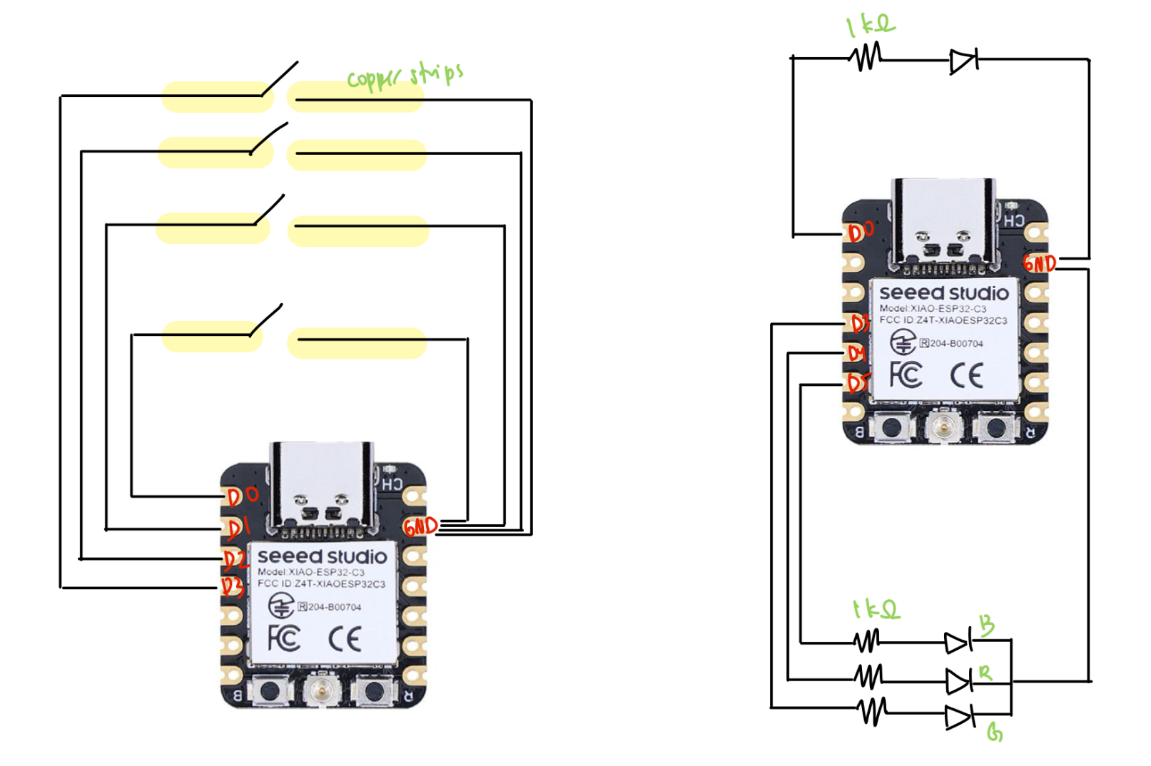
In the meantime, I used a box-cutter to cut pieces out of cardboard and this thick paper I found in the shop. I taped down two pieces of copper to the base for each light switch piece, then a single thick copper strip to the bottom of each piece--this way, whenever a switch piece was put on the board, it would complete the circuit and allow current to pass. I then connected one of the copper strips to ground and the other to a pin, using the pull-up method to detect when the switch was on.
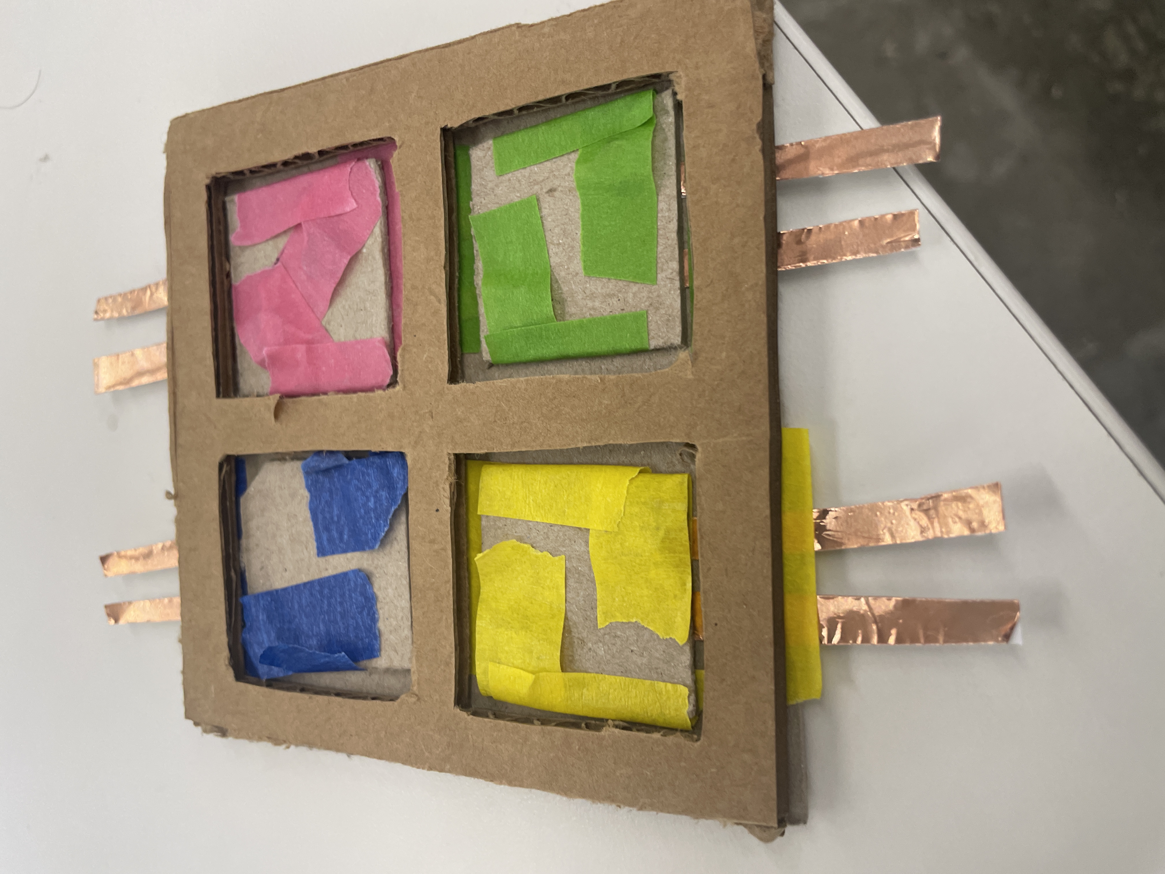
I also attached magnets to secure the pieces to the board such that when placed, they would be correctly oriented to complete the circuit.
For the outputs, I hooked up an RGB light and a normal LED to a separate microcontroller. I also had to solder the headers to another XIAO board, which was difficult (but I eventually got it--Bobby told me to hold my breath so that my hands would shake less). I couldn't find another breadboard, which is why it's all on one board--but the circuits are completely independent.
Finally, I spent some time writing the class code for my light board and the LED lights. After reading next week's documents on the ESP-NOW protocol, I integrated the code with my code from last week for switches and lights. Luckily, I didn't have to do too much debugging to get it to work--I basically just had the switch talking to the lights (one-way communication), where it would send numbers representing on or off for each piece that was on the board. Since I made some changes to this code later, I'll just include the final code in the next part.
Iteration 2: Printed pieces
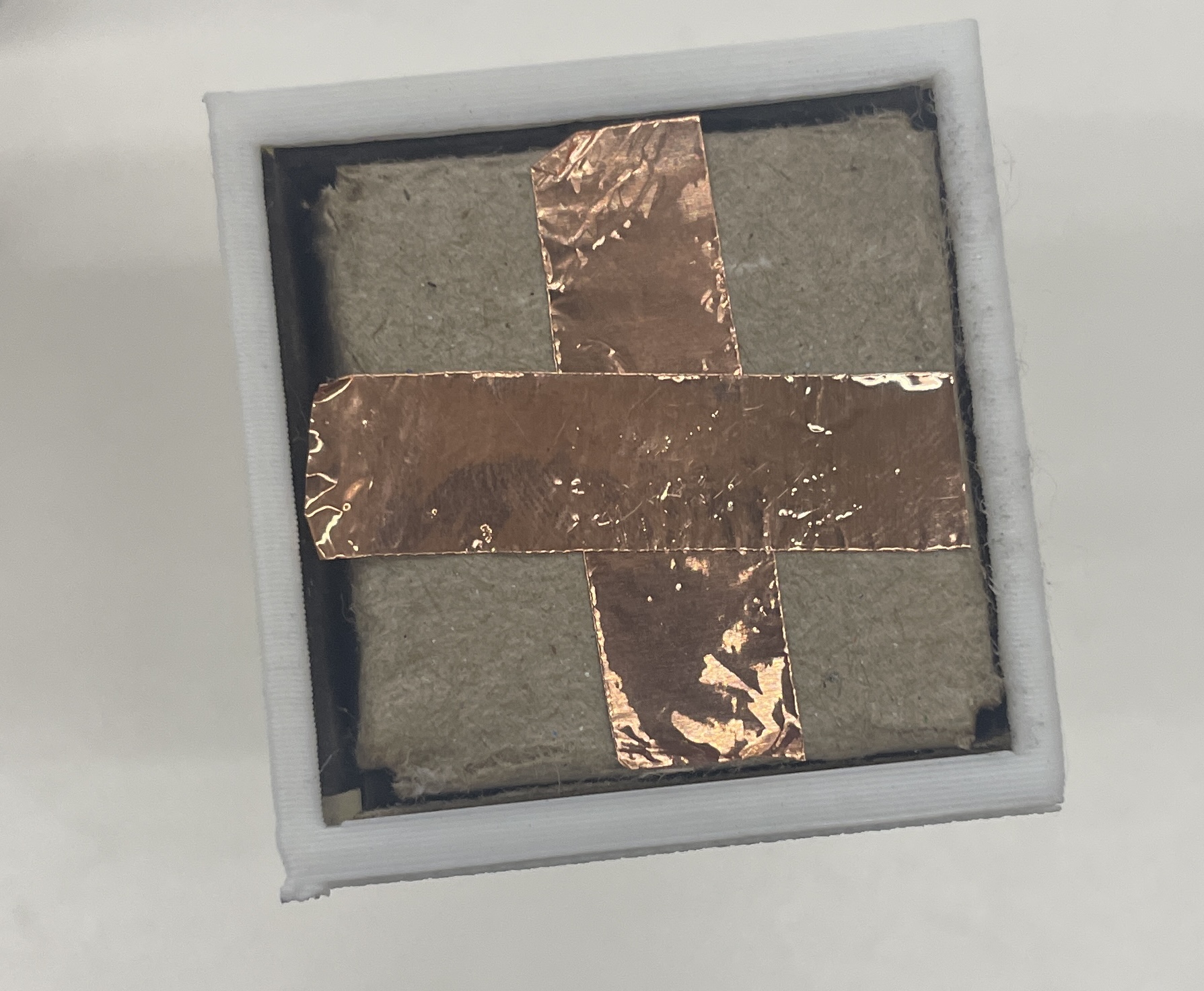
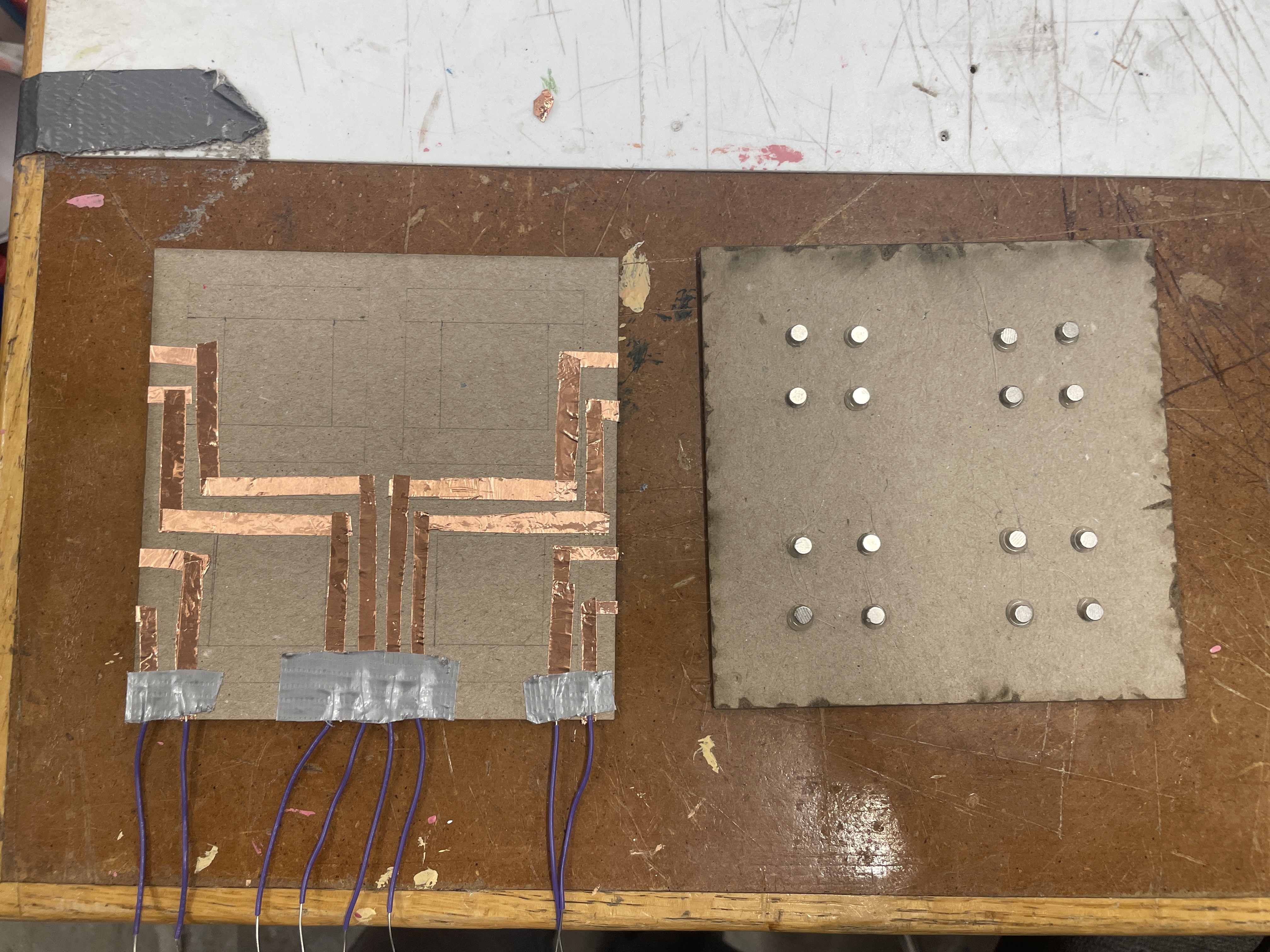
Once my Fusion was back up and running, I 3D my pieces (again) to be 4cm x 4cm. I also redesigned a rudimentary laser-cut board out of wood and the thick paper. I switched from using 2 magnets per piece to using 4, since it was fairly annoying to rotate pieces so that they would stick to the board. I stuck the copper pieces to the board in the same way, but in order to account for additional rotations of the piece, I taped the copper to the bottom of the pieces in a cross shape.
One issue I wanted to resolve from the first iteration was that connecting the copper pieces to the breadboard was really ugly. To try to solve this, I taped down a bunch of copper pieces as circuitry on the backside of the base, and I used a multimeter to test that there was still current through the copper. Though this worked, I still had a lot of trouble connecting the copper pieces to the breadboard, and after a couple hours of trying socket-socket wires, duct taping wires, rewiring my breadboard to be closer to the copper ends, I just gave up and took 8 alligator clips. This is definitely a challenge I'd be interested in solving--especially because my eventual goal is to have a small circuit/PCB just underneath the base.
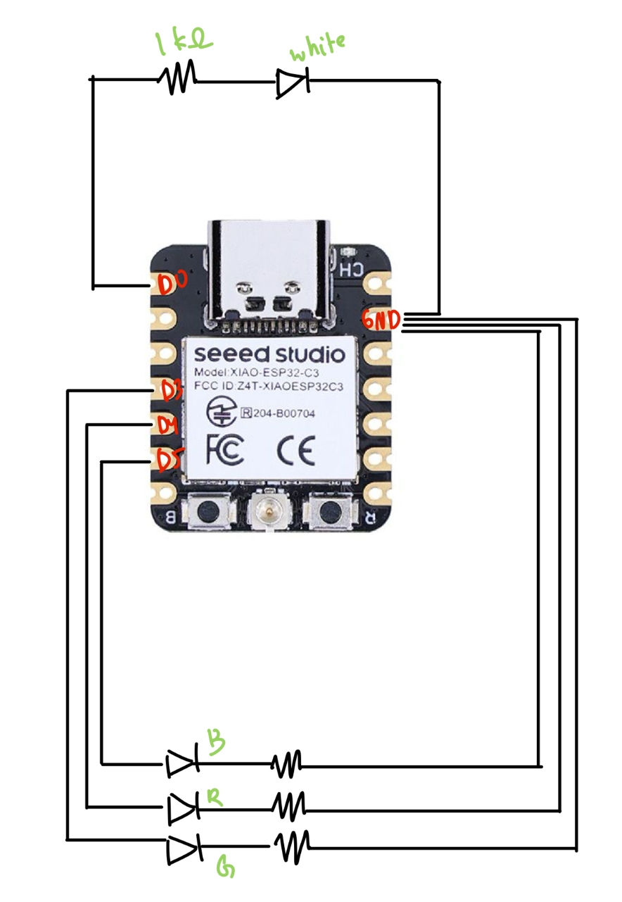
The other major thing I changed was instead of using an RGB LED, I switched to using 4 distinct LEDs to correspond better to my end goal of having each piece control a separate light. This took some minor rewiring, and as far as code changes, I simply switched to using four instances of my LED class instead of the RGB class.
    // final_lights.ino
    #include <esp_now.h>
    #include <WiFi.h>

    // LED pins
    const int ledPin = D0; // Normal LED
    const int redPin = D4; // Red LED
    const int bluePin = D5; // Blue LED
    const int greenPin = D3; // Green LED

    uint8_t broadcastAddress[] = {0x34, 0x85, 0x18, 0x03, 0xF2, 0x3C};

    byte incomingByte;

    // RGB LED Class
    class RGB_LED {
        public:
        RGB_LED(int r, int g, int b) {
            redPin = r;
            greenPin = g;
            bluePin = b;
            pinMode(redPin, OUTPUT);
            pinMode(greenPin, OUTPUT);
            pinMode(bluePin, OUTPUT);
            off();
        }

        void off() {
            digitalWrite(redPin, LOW);
            digitalWrite(greenPin, LOW);
            digitalWrite(bluePin, LOW);
        }

        void red() {
            digitalWrite(redPin, HIGH);
            Serial.println("Red ON");
        }

        void redOff() {
            digitalWrite(redPin, LOW);
        }

        void green() {
            digitalWrite(greenPin, HIGH);
            Serial.println("Green ON");
        }

        void greenOff() {
            digitalWrite(greenPin, LOW);
        }

        void blue() {
            digitalWrite(bluePin, HIGH);
            Serial.println("Blue ON");
        }

        void blueOff() {
            digitalWrite(bluePin, LOW);
        }

        private:
        int redPin, greenPin, bluePin;
    };

    // Normal LED Class
    class LED {
        public:
        LED(int pin) {
            ledPin = pin;
            pinMode(ledPin, OUTPUT);
            off();
        }

        void on() {
            digitalWrite(ledPin, HIGH);
            Serial.println("Normal LED ON");
        }

        void off() {
            digitalWrite(ledPin, LOW);
            Serial.println("Normal LED OFF");
        }

        private:
        int ledPin;
    };

    // Create LED instances
    // RGB_LED rgb(redPin, greenPin, bluePin);
    LED led1(ledPin);
    LED led2(redPin);
    LED led3(bluePin);
    LED led4(greenPin);


    // ESP-NOW Callback for receiving data
    // Callback when data is received (Updated for newer ESP-NOW API)
    void OnDataRecv(const esp_now_recv_info_t *info, const uint8_t *incomingData, int len) {
        memcpy(&incomingByte, incomingData, sizeof(incomingByte));
        Serial.print("Received: ");
        Serial.println(incomingByte);

        // Control LEDs based on received value
        if (incomingByte == '1') {
            led1.on();
        } else if (incomingByte == '2') {
            led2.on();
        } else if (incomingByte == '3') {
            led3.on();
        } else if (incomingByte == '4') {
            led4.on();
        } else if (incomingByte == '5') {
            led1.off();
        } else if (incomingByte == '6') {
            led2.off();
        } else if (incomingByte == '7') {
            led3.off();
        } else if (incomingByte == '8') {
            led4.off();
        }
    }


    void setup() {
        Serial.begin(115200);

        // Set device as a Wi-Fi Station
        WiFi.mode(WIFI_STA);

        // Init ESP-NOW
        if (esp_now_init() != ESP_OK) {
            Serial.println("ESP-NOW Initialization Failed!");
            while (true);
        }

        // Register ESP-NOW receive callback
        esp_now_register_recv_cb(OnDataRecv);

        // turn lights off
        led1.off();
        led2.off();
        led3.off();
        led4.off();
    }

    void loop() {
        // Nothing needed in loop, as data reception triggers LED changes
    }
    // board.ino
    #include <esp_now.h>
    #include <WiFi.h>

    // ESP-NOW Broadcast Address (Receiver MAC Address)
    uint8_t broadcastAddress[] = {0x48, 0x31, 0xB7, 0x3F, 0xBA, 0x10};

    // Variable to store received data
    byte incomingByte;
    byte outgoingByte;

    // Callback when data is sent
    void OnDataSent(const uint8_t *mac_addr, esp_now_send_status_t status) {
        // Serial.print("\r\nLast Packet Send Status:\t");
        // Serial.println(status == ESP_NOW_SEND_SUCCESS ? "Delivery Success" : "Delivery Fail");
    }

    // Callback when data is received
    void OnDataRecv(const esp_now_recv_info_t *info, const uint8_t *incomingData, int len) {
        memcpy(&incomingByte, incomingData, sizeof(incomingByte));
        Serial.print("Bytes received: ");
        Serial.println(len);
        Serial.print("Received data: ");
        Serial.println(incomingByte);
    }


    // Switch Class
    class Switch {
        private:
        int pin;
        char message; // Unique on message per switch
        char off_char;

        public:
        // Constructor
        Switch(int switchPin, char msg, char off_msg) {
            pin = switchPin;
            message = msg;
            off_char = off_msg;
            pinMode(pin, INPUT_PULLUP);
        }

        // Check if switch is pressed
        bool isOn() {
            return digitalRead(pin) == LOW; // LOW means pressed
        }

        // Send ESP-NOW message when pressed
        void sendMessage() {
            if (isOn()) {
                Serial.print("Sending message: ");
                Serial.println(message);
                esp_err_t result = esp_now_send(broadcastAddress, (uint8_t*)&message, sizeof(message));

                if (result == ESP_OK) {
                    Serial.println("Sent with success");
                } else {
                    Serial.println("Error sending the data");
                }
                delay(300); // Avoid rapid multiple sends
            } else {
                Serial.print("Sending message: ");
                Serial.println(off_char);
                esp_err_t result = esp_now_send(broadcastAddress, (uint8_t*)&off_char, sizeof(off_char));

                if (result == ESP_OK) {
                    Serial.println("Sent with success");
                } else {
                    Serial.println("Error sending the data");
                }
                delay(300); // Avoid rapid multiple sends
            }
        }
    };

    // Define switches with unique messages
    Switch switch1(D0, '1', '5');
    Switch switch2(D1, '2', '6');
    Switch switch3(D2, '3', '7');
    Switch switch4(D3, '4', '8');

    void setup() {
        Serial.begin(115200);

        // Set device as a Wi-Fi Station
        WiFi.mode(WIFI_STA);

        // Init ESP-NOW
        if (esp_now_init() != ESP_OK) {
            Serial.println("ESP-NOW Initialization Failed!");
            while (true); // Stop execution if ESP-NOW fails
        }

        // Register send and receive callbacks
        esp_now_register_send_cb(OnDataSent);
        esp_now_register_recv_cb(OnDataRecv);

        // Register Peer
        esp_now_peer_info_t peerInfo;
        memset(&peerInfo, 0, sizeof(peerInfo));
        memcpy(peerInfo.peer_addr, broadcastAddress, 6);
        peerInfo.channel = 0;
        peerInfo.encrypt = false;

        if (esp_now_add_peer(&peerInfo) != ESP_OK) {
            Serial.println("Failed to add peer");
            while (true); // Stop if peer registration fails
        }
    }

    void loop() {
        switch1.sendMessage();
        switch2.sendMessage();
        switch3.sendMessage();
        switch4.sendMessage();
    }
Finally, here's it working!
Here were my files from this week.
Part 4: Circuit Downsizing
[from Week 8]
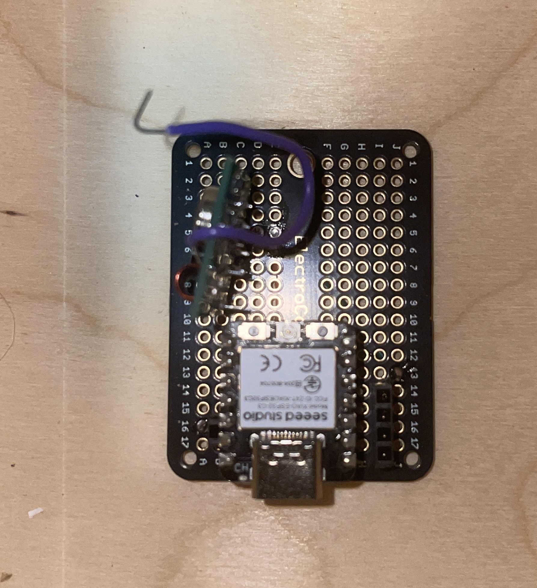
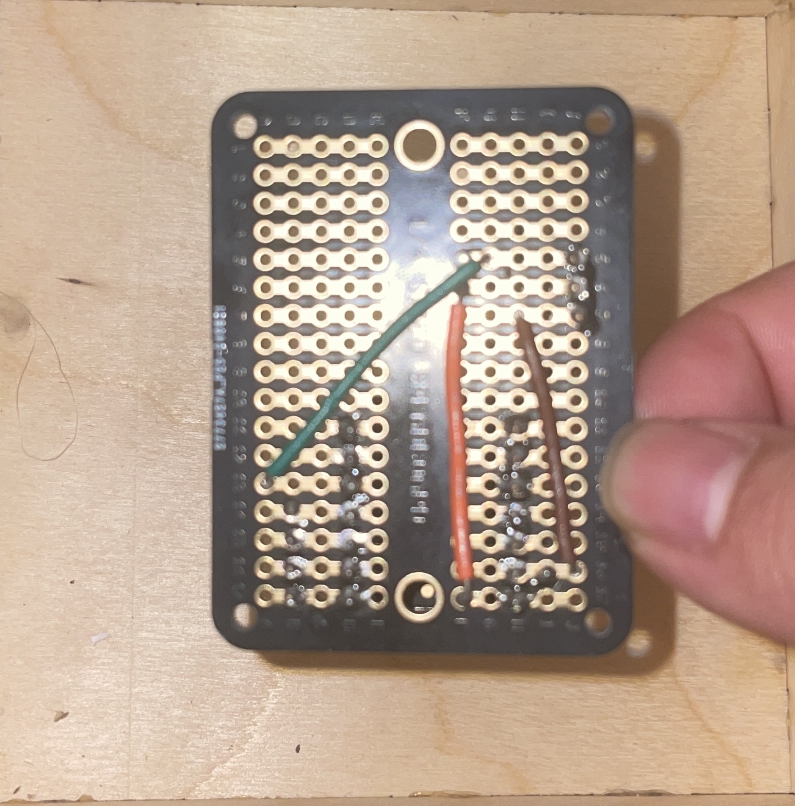
I also did some work to try to make the base less wire-y, and I'm planning on pseudo-milling a PCB board, except the board is just a couple pieces of copper plates and holes to solder wires to from beneath, so that I can hide wires, etc. in a base. In the future, Bobby said I could send off a 2-sided PCB design to be manufactured, but if I can mill out the copper, this would certainly be an improvement.
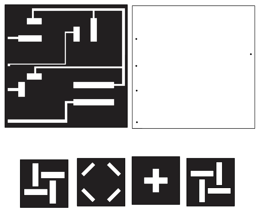
I also designed the base so that each of the four slots can only be turned on by a specific piece (in any of the 4 orientations/rotations). This was one of my stretch goals--I will also want the figurine part of each piece to be detachable, so that users can swap out which figure corresponds to which square/slot in the base (useful if they want certain switches to correspond to different locations in their room, for instance).
Part 5: Integrated Project
For this iteration, I wanted to get the core parts of the final project down, including using the RF smart plug and more finalized copper pieces. I struggled a lot with getting good copper connections.
RF Smart Plug
First, to communicate with the RF smart plug, I had to purchase 433MHz RF transmitter and receivers . Next, I configured the receiver to listen for the RF signal from the remote (sketch below), with help from this Random Nerd Tutorials post.
#include <RCSwitch.h>

// Initialize rc-switch objects
RCSwitch mySwitchReceiver = RCSwitch();


void setup() {
    Serial.begin(9600); // Start Serial Monitor for debugging

    // Initialize transmitter and receiver
    mySwitchReceiver.enableReceive(7); // Receiver connected to GPIO 7
    delay(1000); // ensure everything is initialized

}

void loop() {
    // Check if the receiver has received data
    if (mySwitchReceiver.available()) {
        long receivedValue = mySwitchReceiver.getReceivedValue();
        Serial.print("Received Value: ");
        Serial.println(receivedValue);
        Serial.print("Protocol: ");
        Serial.println(mySwitchReceiver.getReceivedProtocol());
        Serial.print("Bit length: ");
        Serial.println(mySwitchReceiver.getReceivedBitlength());
        Serial.print("Pulse length: ");
        Serial.println(mySwitchReceiver.getReceivedDelay());

        // Reset the receiver to prepare for the next message
        mySwitchReceiver.resetAvailable();
    }

    delay(5000); // Wait 5 seconds before checking again
}
I determined that the protocol was 1, bit length was 24, and the pulse length was 180. I also got the following transmit codes:
- 1 on: 12876364
- 1 off: 12876356
- 2 on: 12876362
- 2 off: 12876354
- 3 on: 12876361
- 3 off: 12876353
- 4 on: 12876365
- 4 off: 12876357
- 5 on: 12876363
- 5 off: 12876355
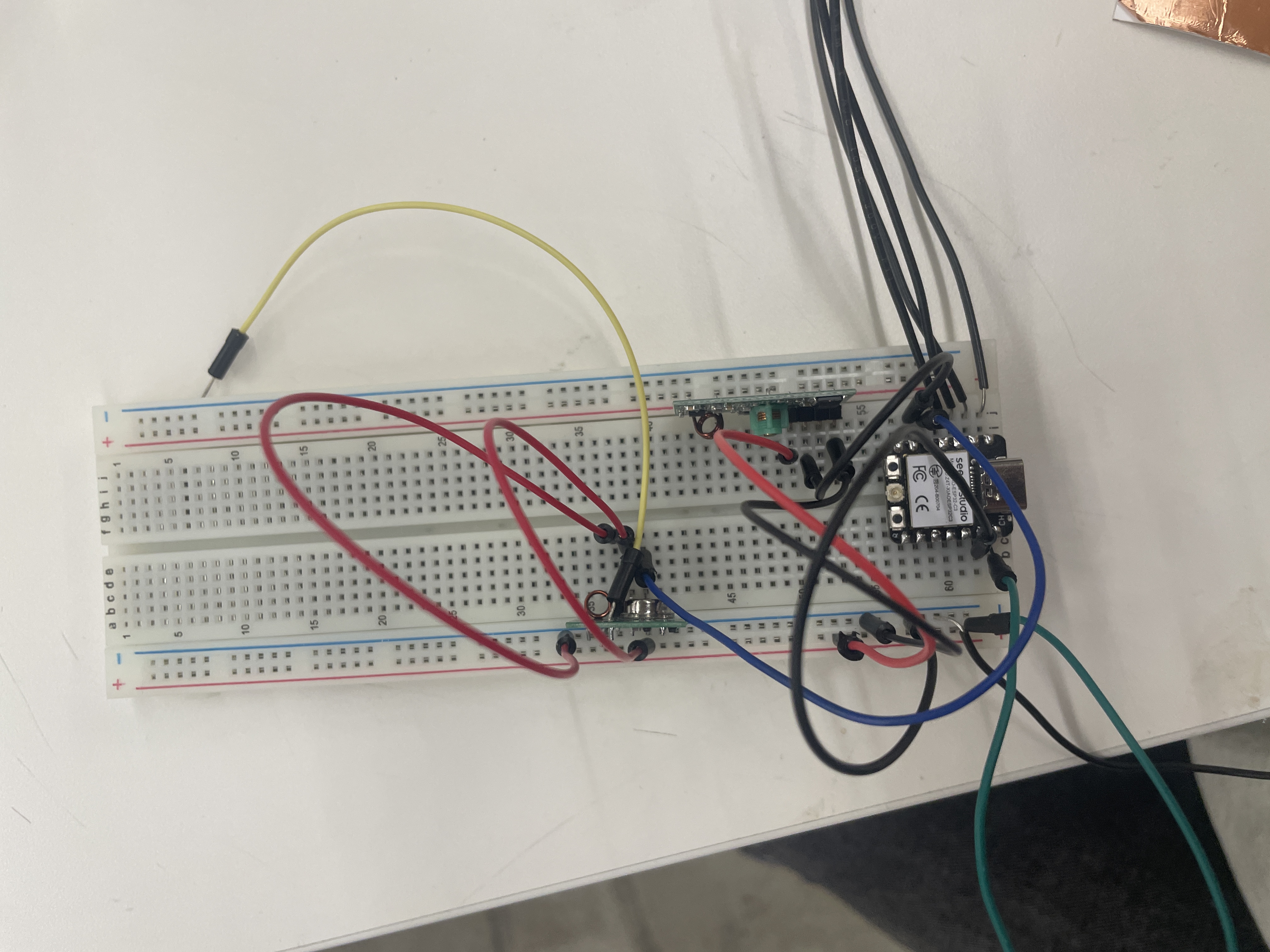
Next, I tried to get the transmitter to turn on the relays/smart plugs. I first tried to just use a sender sketch, but nothing happened, and I struggled to troubleshoot because I didn't have my receiver set up to make sure that the transmitter was working. I tried to set up two separate microcontrollers, one for the receiver and one for the transmitter (I had the ESP-WROOM from the drawing machine), but then I couldn't upload code to the ESP-WROOM, so I then realized I could just wire both receiver and transmitter to a single microcontroller. The end-result sketch is below; it just echoes receiver/transmits.
 #include <RCSwitch.h>

// Initialize rc-switch objects
RCSwitch mySwitchReceiver = RCSwitch();
RCSwitch mySwitchTransmitter = RCSwitch();

// Transmitting code (use the same value as in the receiver)
long transmitValue = 12876364; // This is the code you're transmitting

void setup() {
    Serial.begin(9600); // Start Serial Monitor for debugging

    // Initialize transmitter and receiver
    mySwitchReceiver.enableReceive(7); // Receiver connected to GPIO 4
    mySwitchTransmitter.enableTransmit(6); // Transmitter connected to GPIO 5

    mySwitchTransmitter.setProtocol(1);
    mySwitchTransmitter.setPulseLength(180);
    mySwitchTransmitter.setRepeatTransmit(10);

    delay(1000); // Short delay to ensure everything is initialized
    mySwitchTransmitter.send(transmitValue, 24);

}

void loop() {
    // Check if the receiver has received data
    if (mySwitchReceiver.available()) {
        long receivedValue = mySwitchReceiver.getReceivedValue();
        Serial.print("Received Value: ");
        Serial.println(receivedValue);
        Serial.print("Protocol: ");
        Serial.println(mySwitchReceiver.getReceivedProtocol());
        Serial.print("Bit length: ");
        Serial.println(mySwitchReceiver.getReceivedBitlength());
        Serial.print("Pulse length: ");
        Serial.println(mySwitchReceiver.getReceivedDelay());

        // Reset the receiver to prepare for the next message
        mySwitchReceiver.resetAvailable();

        // If the received value matches the target, transmit the same code
        if (receivedValue == transmitValue) {
        Serial.println("Transmitting the same value back...");
        mySwitchTransmitter.send(transmitValue, 24); // Send the same value (24 is the pulse length in bits)
        }
    }

    // Optionally, periodically transmit the value even if no signal is received
    // Uncomment the lines below if you want to keep sending the code every few seconds.
    Serial.println("Transmitting...");
    mySwitchTransmitter.send(transmitValue, 24);
    delay(5000); // Wait 5 seconds before retransmitting
}
I had to make a couple of changes before arriving at the code snippet above, as well as some hardware fixes. First, I noticed that the receiver only sometimes got the code from the transmitter; I swapped a couple of transmitters and this was a very consistent problem. After digging through Amazon reviews, I figured out that the transmitter needed an antenna, and Google said that a loose wire would suffice, so I stuck a wire through the antenna hole and sends were much more reliably received by the receiver. However, the relays still weren't turning on, but the transmit codes were correct (a.k.a. equivalent to what the remote was sending). I noticed that the pulse length wasn't what I had set. I consulted Stack Exchange and switched around two lines of code: the protocol must be set before dictating the pulse length. And then finally my relays turned on.
Copper Milling
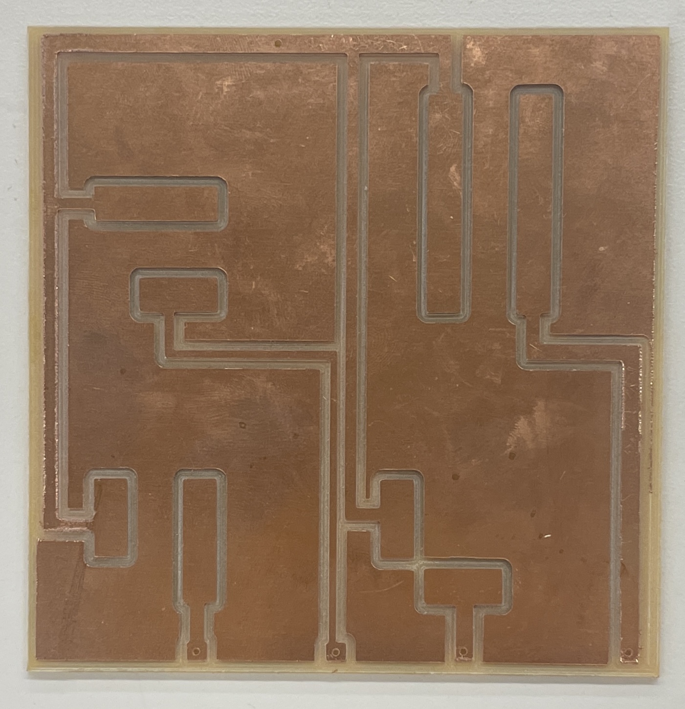
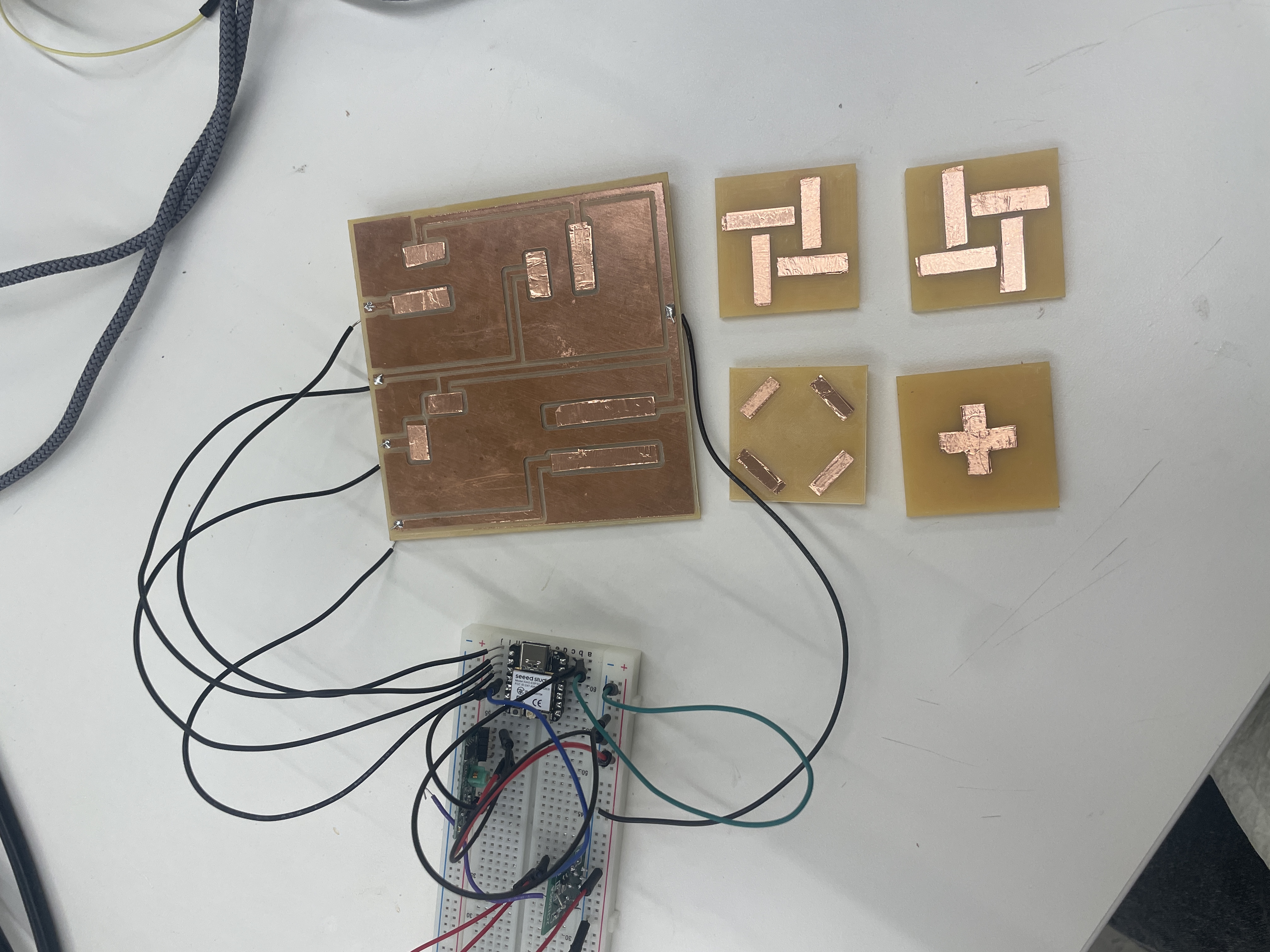
I spent a couple hours milling out the copper pieces from my Adobe Illustrator files above, with a lot of help from Bobby! I quickly realized that the copper was almost too flat, so it was extremely sensitive to any curvature from the copper base, meaning that the copper connection was extremely finicky. When testing the connection, I was at first just using alligator clips on the copper base, but I noticed that this would scratch at the copper, so I soldered some wires through the base of the piece so that the alligators wouldn't scratch.
Without any additional fixes, 2 of my pieces could form stable copper connections, and the other two had to be held down with a lot of force before there was any current. I then experimented with using 4 magnets (one in each corner) to hold the pieces down, but I couldn't get the alignment correct: when one orientation formed a solid connection, turning the piece by 90 degrees resulted in a bad connection, so I ditched this idea because if I'd wanted to do this, I should have milled the magnet holes into the base piece. [Also note that to get this to work, all magnets have to be in the same orientation, so I marked the tops of all the magnets so that when attaching, I didn't glue the wrong side down.]
I then added some copper sheets to each of the pieces, which worked for 3 of the pieces in all rotations, but the fourth piece was still really finicky. I then added copper sheets to the two copper strips on the base (for each of the pieces), and then used a strong magnet taped to the centers of each piece, and this seemed to work ok for the pieces. Sometimes the pieces still have to be rotated before the connection is registered, but once the orientation is correct, the connection stays consistent, which seems good enough to me (especially once I add the frame back to the base piece, which should help with rotation/alignment).
Finally, I integrated the RF relay code into my existing code from the MVP; I decided to keep the receiver on just in case I still had to debug any sends.
#include <RCSwitch.h>

int transmitterPin = 6; // GPIO 6
int receiverPin = 7; // GPIO 7
int switch1Pin = D0;
int switch2Pin = D1;
int switch3Pin = D2;
int switch4Pin = D3;


RCSwitch mySwitchTransmitter = RCSwitch();
RCSwitch mySwitchReceiver = RCSwitch();


// Switch Class
class Switch {
    private:
        int pin;
        long message; // Unique on message per switch
        long off_message;

    public:
        // Constructor
        Switch(int switchPin, long msg, long off_msg) {
            pin = switchPin;
            message = msg;
            off_message = off_msg;
            pinMode(pin, INPUT_PULLUP);
        }

        // Check if switch is pressed
        bool isOn() {
            return digitalRead(pin) == LOW; // LOW means pressed
        }

        // Send ESP-NOW message when pressed
        void sendMessage() {
            if (isOn()) {
                Serial.print(pin);
                Serial.print(" | Sending on message: ");
                Serial.println(message);

                mySwitchTransmitter.send(message, 24);
                delay(300); // Avoid rapid multiple sends
            } else {
                Serial.print("Sending off message: ");
                Serial.println(off_message);

                mySwitchTransmitter.send(off_message, 24);
                delay(300); // Avoid rapid multiple sends
            }
        }
};


Switch switch1(switch1Pin, 12876364, 12876356);
Switch switch2(switch2Pin, 12876361, 12876353);
Switch switch3(switch3Pin, 12876365, 12876357);
Switch switch4(switch4Pin, 12876363, 12876355);


void setup() {
    Serial.begin(9600); // Start Serial Monitor for debugging

    // Initialize transmitter and receiver
    mySwitchTransmitter.enableTransmit(transmitterPin);
    mySwitchReceiver.enableReceive(receiverPin);

    mySwitchTransmitter.setProtocol(1);
    mySwitchTransmitter.setPulseLength(180);
    mySwitchTransmitter.setRepeatTransmit(10);

    delay(1000); // Short delay to ensure everything is initialized
}

void loop() {
    switch1.sendMessage();
    switch2.sendMessage();
    switch3.sendMessage();
    switch4.sendMessage();
    if (mySwitchReceiver.available()) {
        long receivedValue = mySwitchReceiver.getReceivedValue();
        Serial.print("Received Value: ");
        Serial.println(receivedValue);
        Serial.print("Protocol: ");
        Serial.println(mySwitchReceiver.getReceivedProtocol());
        Serial.print("Bit length: ");
        Serial.println(mySwitchReceiver.getReceivedBitlength());
        Serial.print("Pulse length: ");
        Serial.println(mySwitchReceiver.getReceivedDelay());

        // Reset the receiver to prepare for the next message
        mySwitchReceiver.resetAvailable();
    }
}
Integration Result
Part 6: Final Version
For the last part of my project, I just wanted to ensure a working product and integrate it with my previous lamp pieces. I also wanted to enclose the base/electronics to look more polished. The only new feature I built was interchangeable pieces, so that a user could swap out the figurine part of the piece.
First, I soldered the circuit into a protoboard, and I chose to solder sockets for the arduino as well as any wires coming from the base. While it may have been more secure to solder in the wires from the board, I knew that it would be difficult to swap out the arduino if the entire board couldn't be removed from beneath the base, as it sits in a little box.
Next I worked on designing swappable pieces. For this, I chose to use slidable pieces that could swap out of the base (as the pieces are one-to-one mapped with the copper-milled base, as in a certain piece can only turn on a single square in a base). After a couple of mini-prints, I realized 0.3mm was the ideal tolerance for the pieces to slide in and out of the base. However, sometimes it was too much tolerance and led to the pieces falling out, so I added a small hole to glue a magnet to the base of the figurines. This worked because the piece bases already had magnets to manage connections to the base.
The most annoying part after gluing in magnets to the pieces and assembling them was then assembling magnets on the base. The copper-to-copper connectionw as extremely fickle, so I spent a really long time playing around with where to put the magnets as well as retaping little copper strips to try and improve the connection. I was moderately successful, but sometimes the final product still requires a lot of fiddling before the connection is made.
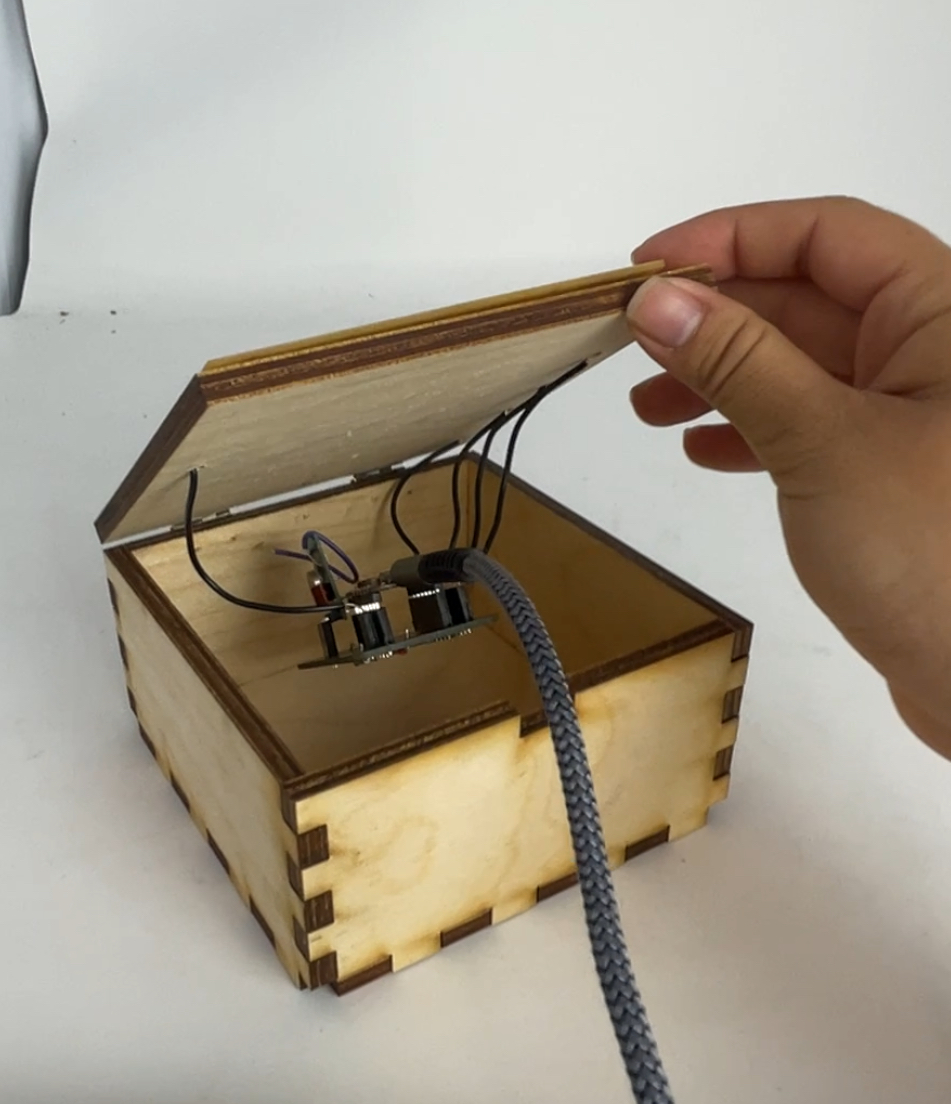
The last step was to make the box for the base. I used a laser cutter to cut out a finger-jointed box, held together with wood glue. In my first iteration, I used a drill press to make holes for the wires from the copper-milled base, and I also forgot to make a small hole for the charging cable. My second iteration was more successful (but only needed because I wood-glued the first iteration way too soon). After assembling the box, inserting hinges, and attaching the protoboard, my project was 99% done.
Finally, I made really small tweaks to my code. In an effort to limit how many sends my arduino was making to the relays (it felt like good practice), I just had the arduino store the last state of each relay so that it would only send a signal if the state changed.
#include <RCSwitch.h>

int transmitterPin = 6; // GPIO 6
int receiverPin = 7; // GPIO 7
int switch1Pin = D0;
int switch2Pin = D1;
int switch3Pin = D2;
int switch4Pin = D3;


RCSwitch mySwitchTransmitter = RCSwitch();


// Switch Class
class Switch {
private:
    int pin;
    long message; // Unique "on" message per switch
    long off_message; // Unique "off" message per switch
    bool lastState; // Last known state of the switch

public:
    // Constructor
    Switch(int switchPin, long msg, long off_msg) {
        pin = switchPin;
        message = msg;
        off_message = off_msg;
        pinMode(pin, INPUT_PULLUP);
        lastState = digitalRead(pin) == LOW; // Initial state
    }

    // Check if switch is currently pressed
    bool isOn() {
        return digitalRead(pin) == LOW; // LOW means pressed
    }

    // Send ESP-NOW message only if the state has changed
    void update() {
        bool currentState = isOn();
        if (currentState != lastState) {
            lastState = currentState; // Update the stored state

            if (currentState) {
                mySwitchTransmitter.send(message, 24);
            } else {
                mySwitchTransmitter.send(off_message, 24);
            }
            delay(300); // Avoid rapid multiple sends
        }
    }
};


Switch switch1(switch1Pin, 12876364, 12876356);
Switch switch2(switch2Pin, 12876361, 12876353);
Switch switch3(switch3Pin, 12876365, 12876357);
Switch switch4(switch4Pin, 12876363, 12876355);


void setup() {
    Serial.begin(9600); // Start Serial Monitor for debugging

    // Initialize transmitter and receiver
    mySwitchTransmitter.enableTransmit(transmitterPin);
    mySwitchReceiver.enableReceive(receiverPin);

    mySwitchTransmitter.setProtocol(1);
    mySwitchTransmitter.setPulseLength(180);
    mySwitchTransmitter.setRepeatTransmit(10);

    delay(1000); // Short delay to ensure everything is initialized

}

void loop() {
    switch1.update();
    switch2.update();
    switch3.update();
    switch4.update();
}
And here is the final product! (Same as the demo at the top.)