Iteration 1: Cardboard cutouts
When I started working on this project, I was originally planning to laser cut my pieces, but my Fusion software completely broke down. I spent two hours completely uninstalling it, then reinstalling it, and I figured out I had to install it in admin mode (hold control while clicking the installer). I kept getting a permissions error when I was reinstalling the first couple of times, even though the folders had full read/write access, so I'm not sure what admin mode additionally added to the installation process, but it worked.
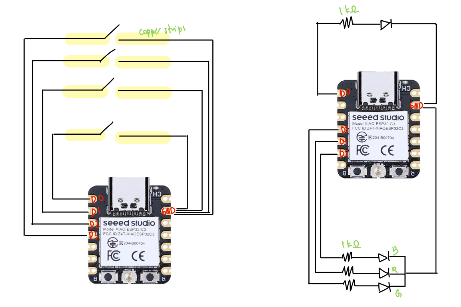
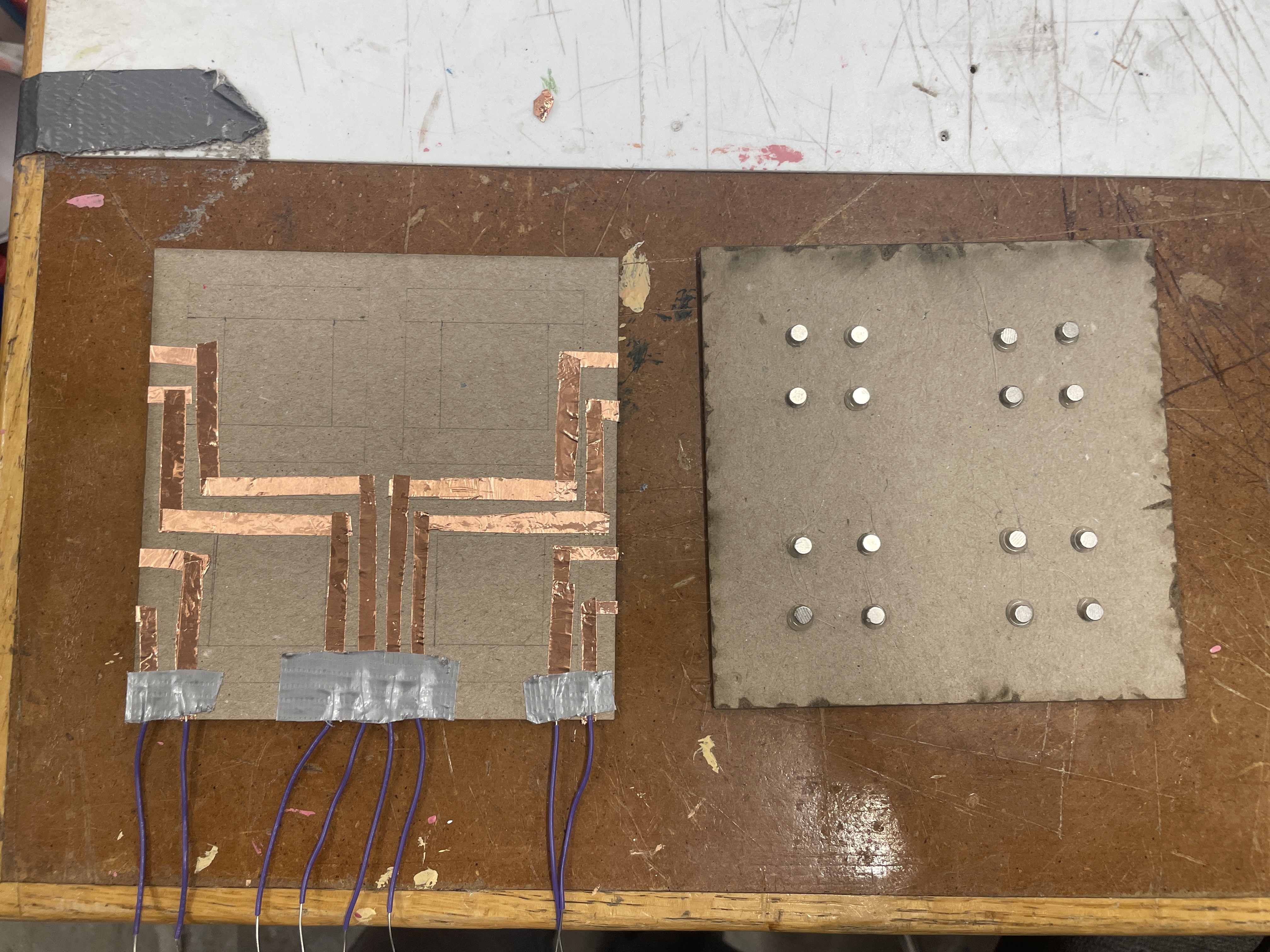
In the meantime, I used a box-cutter to cut pieces out of cardboard and this thick paper I found in the shop. I taped down two pieces of copper to the base for each light switch piece, then a single thick copper strip to the bottom of each piece--this way, whenever a switch piece was put on the board, it would complete the circuit and allow current to pass. I then connected one of the copper strips to ground and the other to a pin, using the pull-up method to detect when the switch was on.
I also attached magnets to secure the pieces to the board such that when placed, they would be correctly oriented to complete the circuit.
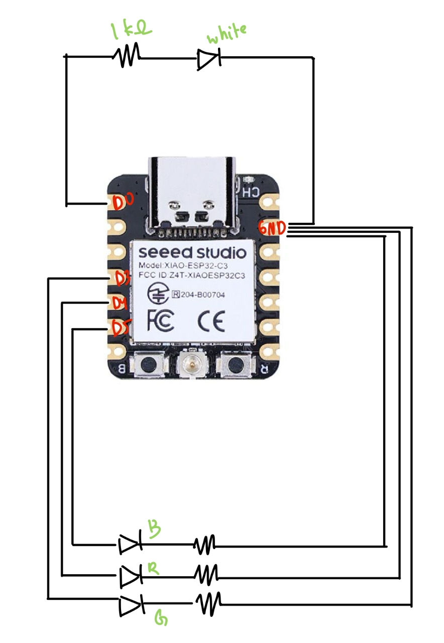
For the outputs, I hooked up an RGB light and a normal LED to a separate microcontroller. I also had to solder the headers to another XIAO board, which was difficult (but I eventually got it--Bobby told me to hold my breath so that my hands would shake less). I couldn't find another breadboard, which is why it's all on one board--but the circuits are completely independent.
Finally, I spent some time writing the class code for my light board and the LED lights. After reading next week's documents on the ESP-NOW protocol, I integrated the code with my code from last week for switches and lights. Luckily, I didn't have to do too much debugging to get it to work--I basically just had the switch talking to the lights (one-way communication), where it would send numbers representing on or off for each piece that was on the board. Since I made some changes to this code later, I'll just include the final code in the next part.
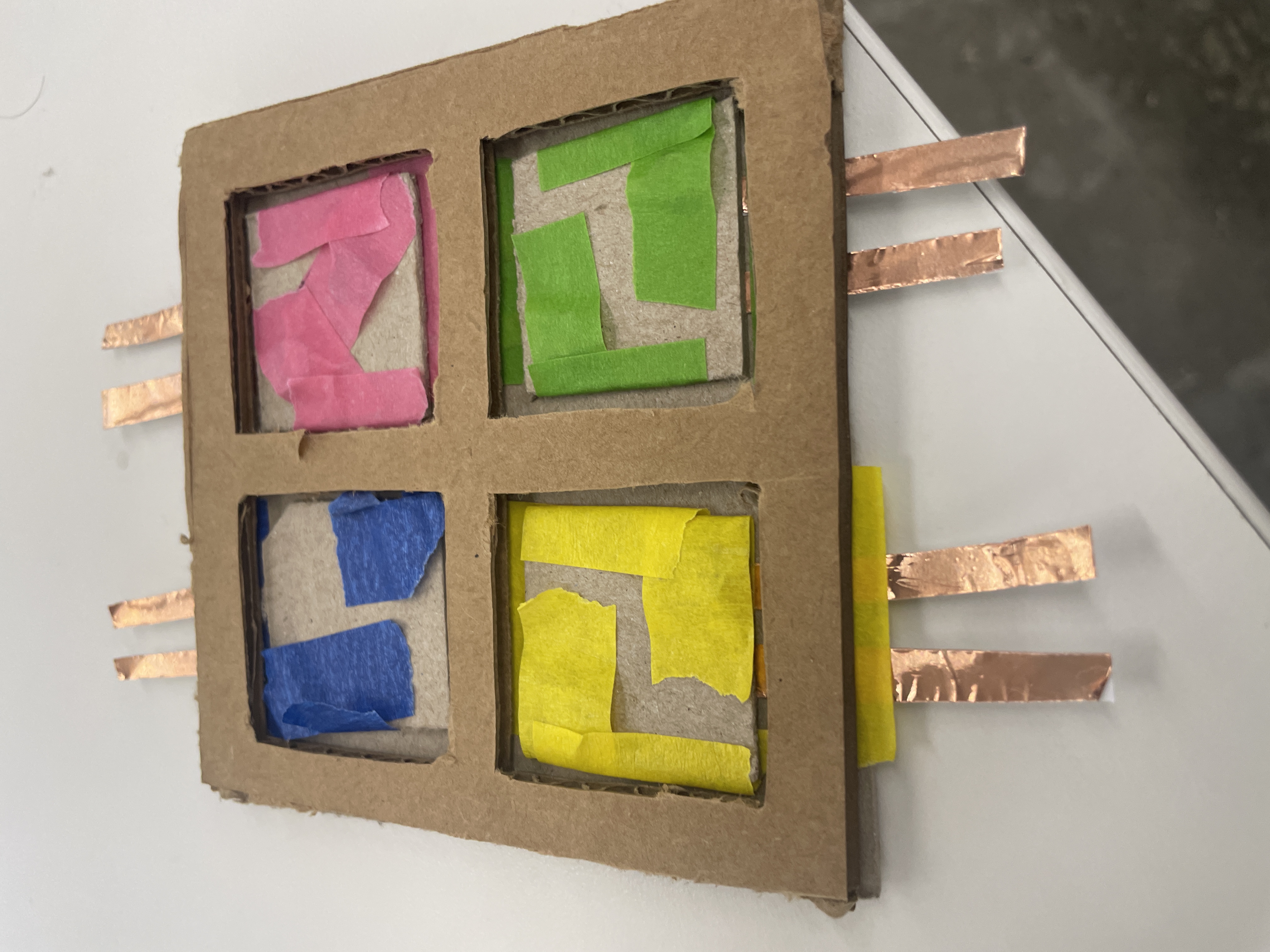
Iteration 2: Printed pieces
Once my Fusion was back up and running, I 3D my pieces (again) to be 4cm x 4cm. I also redesigned a rudimentary laser-cut board out of wood and the thick paper. I switched from using 2 magnets per piece to using 4, since it was fairly annoying to rotate pieces so that they would stick to the board. I stuck the copper pieces to the board in the same way, but in order to account for additional rotations of the piece, I taped the copper to the bottom of the pieces in a cross shape.
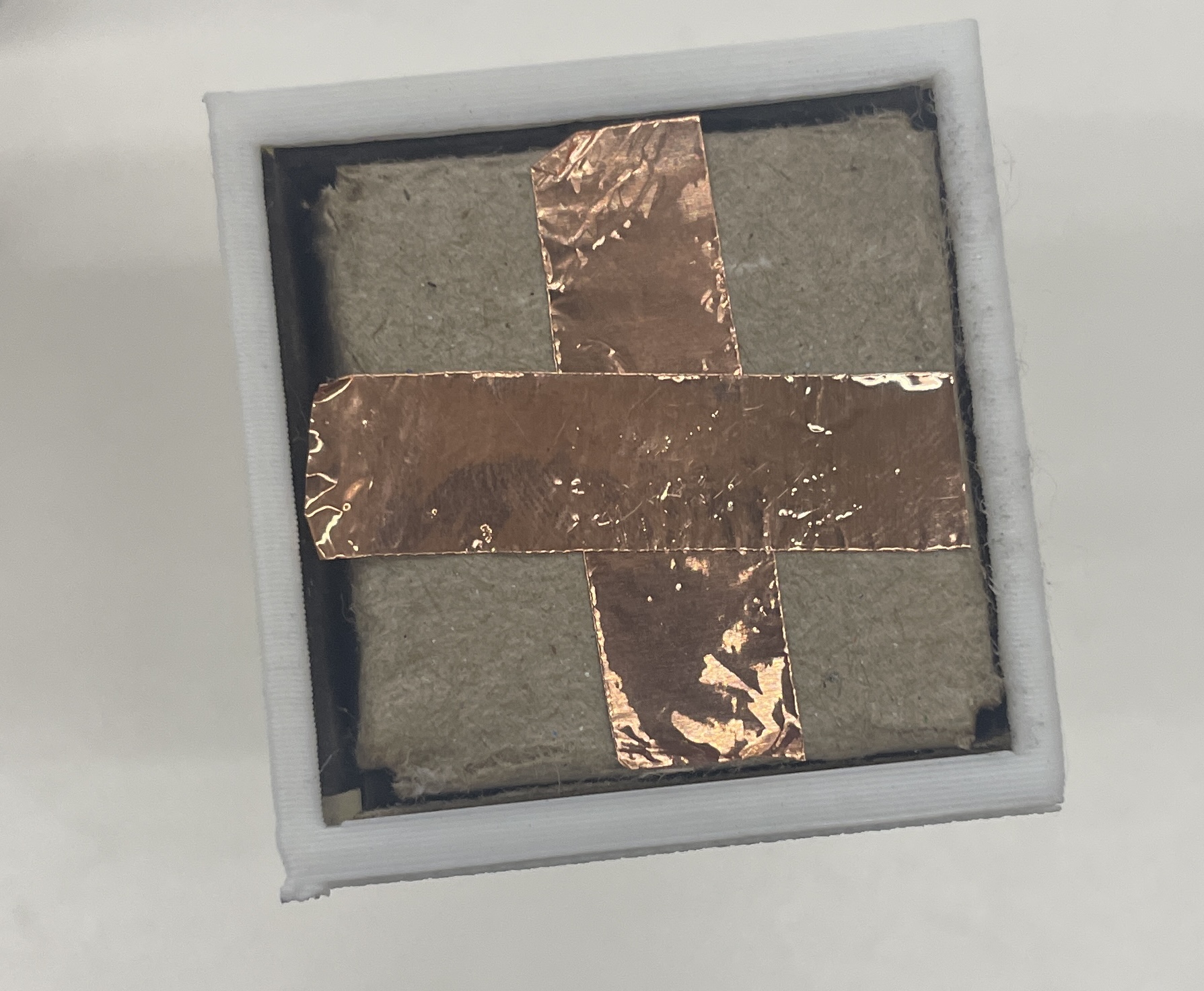
One issue I wanted to resolve from the first iteration was that connecting the copper pieces to the breadboard was really ugly. To try to solve this, I taped down a bunch of copper pieces as circuitry on the backside of the base, and I used a multimeter to test that there was still current through the copper. Though this worked, I still had a lot of trouble connecting the copper pieces to the breadboard, and after a couple hours of trying socket-socket wires, duct taping wires, rewiring my breadboard to be closer to the copper ends, I just gave up and took 8 alligator clips. This is definitely a challenge I'd be interested in solving--especially because my eventual goal is to have a small circuit/PCB just underneath the base.
The other major thing I changed was instead of using an RGB LED, I switched to using 4 distinct LEDs to correspond better to my end goal of having each piece control a separate light. This took some minor rewiring, and as far as code changes, I simply switched to using four instances of my LED class instead of the RGB class.
// final_lights.ino
#include <esp_now.h>
#include <WiFi.h>

// LED pins
const int ledPin = D0; // Normal LED
const int redPin = D4; // Red LED
const int bluePin = D5; // Blue LED
const int greenPin = D3; // Green LED

uint8_t broadcastAddress[] = {0x34, 0x85, 0x18, 0x03, 0xF2, 0x3C};

byte incomingByte;

// RGB LED Class
class RGB_LED {
    public:
    RGB_LED(int r, int g, int b) {
        redPin = r;
        greenPin = g;
        bluePin = b;
        pinMode(redPin, OUTPUT);
        pinMode(greenPin, OUTPUT);
        pinMode(bluePin, OUTPUT);
        off();
    }

    void off() {
        digitalWrite(redPin, LOW);
        digitalWrite(greenPin, LOW);
        digitalWrite(bluePin, LOW);
    }

    void red() {
        digitalWrite(redPin, HIGH);
        Serial.println("Red ON");
    }

    void redOff() {
        digitalWrite(redPin, LOW);
    }

    void green() {
        digitalWrite(greenPin, HIGH);
        Serial.println("Green ON");
    }

    void greenOff() {
        digitalWrite(greenPin, LOW);
    }

    void blue() {
        digitalWrite(bluePin, HIGH);
        Serial.println("Blue ON");
    }

    void blueOff() {
        digitalWrite(bluePin, LOW);
    }

    private:
    int redPin, greenPin, bluePin;
};

// Normal LED Class
class LED {
    public:
    LED(int pin) {
        ledPin = pin;
        pinMode(ledPin, OUTPUT);
        off();
    }

    void on() {
        digitalWrite(ledPin, HIGH);
        Serial.println("Normal LED ON");
    }

    void off() {
        digitalWrite(ledPin, LOW);
        Serial.println("Normal LED OFF");
    }

    private:
    int ledPin;
};

// Create LED instances
// RGB_LED rgb(redPin, greenPin, bluePin);
LED led1(ledPin);
LED led2(redPin);
LED led3(bluePin);
LED led4(greenPin);


// ESP-NOW Callback for receiving data
// Callback when data is received (Updated for newer ESP-NOW API)
void OnDataRecv(const esp_now_recv_info_t *info, const uint8_t *incomingData, int len) {
    memcpy(&incomingByte, incomingData, sizeof(incomingByte));
    Serial.print("Received: ");
    Serial.println(incomingByte);

    // Control LEDs based on received value
    if (incomingByte == '1') {
        led1.on();
    } else if (incomingByte == '2') {
        led2.on();
    } else if (incomingByte == '3') {
        led3.on();
    } else if (incomingByte == '4') {
        led4.on();
    } else if (incomingByte == '5') {
        led1.off();
    } else if (incomingByte == '6') {
        led2.off();
    } else if (incomingByte == '7') {
        led3.off();
    } else if (incomingByte == '8') {
        led4.off();
    }
}


void setup() {
    Serial.begin(115200);

    // Set device as a Wi-Fi Station
    WiFi.mode(WIFI_STA);

    // Init ESP-NOW
    if (esp_now_init() != ESP_OK) {
        Serial.println("ESP-NOW Initialization Failed!");
        while (true);
    }

    // Register ESP-NOW receive callback
    esp_now_register_recv_cb(OnDataRecv);

    // turn lights off
    led1.off();
    led2.off();
    led3.off();
    led4.off();
}

void loop() {
    // Nothing needed in loop, as data reception triggers LED changes
}
// board.ino
#include <esp_now.h>
#include <WiFi.h>

// ESP-NOW Broadcast Address (Receiver MAC Address)
uint8_t broadcastAddress[] = {0x48, 0x31, 0xB7, 0x3F, 0xBA, 0x10};

// Variable to store received data
byte incomingByte;
byte outgoingByte;

// Callback when data is sent
void OnDataSent(const uint8_t *mac_addr, esp_now_send_status_t status) {
    // Serial.print("\r\nLast Packet Send Status:\t");
    // Serial.println(status == ESP_NOW_SEND_SUCCESS ? "Delivery Success" : "Delivery Fail");
}

// Callback when data is received
void OnDataRecv(const esp_now_recv_info_t *info, const uint8_t *incomingData, int len) {
    memcpy(&incomingByte, incomingData, sizeof(incomingByte));
    Serial.print("Bytes received: ");
    Serial.println(len);
    Serial.print("Received data: ");
    Serial.println(incomingByte);
}


// Switch Class
class Switch {
    private:
    int pin;
    char message; // Unique on message per switch
    char off_char;

    public:
    // Constructor
    Switch(int switchPin, char msg, char off_msg) {
        pin = switchPin;
        message = msg;
        off_char = off_msg;
        pinMode(pin, INPUT_PULLUP);
    }

    // Check if switch is pressed
    bool isOn() {
        return digitalRead(pin) == LOW; // LOW means pressed
    }

    // Send ESP-NOW message when pressed
    void sendMessage() {
        if (isOn()) {
            Serial.print("Sending message: ");
            Serial.println(message);
            esp_err_t result = esp_now_send(broadcastAddress, (uint8_t*)&message, sizeof(message));

            if (result == ESP_OK) {
                Serial.println("Sent with success");
            } else {
                Serial.println("Error sending the data");
            }
            delay(300); // Avoid rapid multiple sends
        } else {
            Serial.print("Sending message: ");
            Serial.println(off_char);
            esp_err_t result = esp_now_send(broadcastAddress, (uint8_t*)&off_char, sizeof(off_char));

            if (result == ESP_OK) {
                Serial.println("Sent with success");
            } else {
                Serial.println("Error sending the data");
            }
            delay(300); // Avoid rapid multiple sends
        }
    }
};

// Define switches with unique messages
Switch switch1(D0, '1', '5');
Switch switch2(D1, '2', '6');
Switch switch3(D2, '3', '7');
Switch switch4(D3, '4', '8');

void setup() {
    Serial.begin(115200);

    // Set device as a Wi-Fi Station
    WiFi.mode(WIFI_STA);

    // Init ESP-NOW
    if (esp_now_init() != ESP_OK) {
        Serial.println("ESP-NOW Initialization Failed!");
        while (true); // Stop execution if ESP-NOW fails
    }

    // Register send and receive callbacks
    esp_now_register_send_cb(OnDataSent);
    esp_now_register_recv_cb(OnDataRecv);

    // Register Peer
    esp_now_peer_info_t peerInfo;
    memset(&peerInfo, 0, sizeof(peerInfo));
    memcpy(peerInfo.peer_addr, broadcastAddress, 6);
    peerInfo.channel = 0;
    peerInfo.encrypt = false;

    if (esp_now_add_peer(&peerInfo) != ESP_OK) {
        Serial.println("Failed to add peer");
        while (true); // Stop if peer registration fails
    }
}

void loop() {
    switch1.sendMessage();
    switch2.sendMessage();
    switch3.sendMessage();
    switch4.sendMessage();
}
Finally, here's it working!
Here were my files from this week.
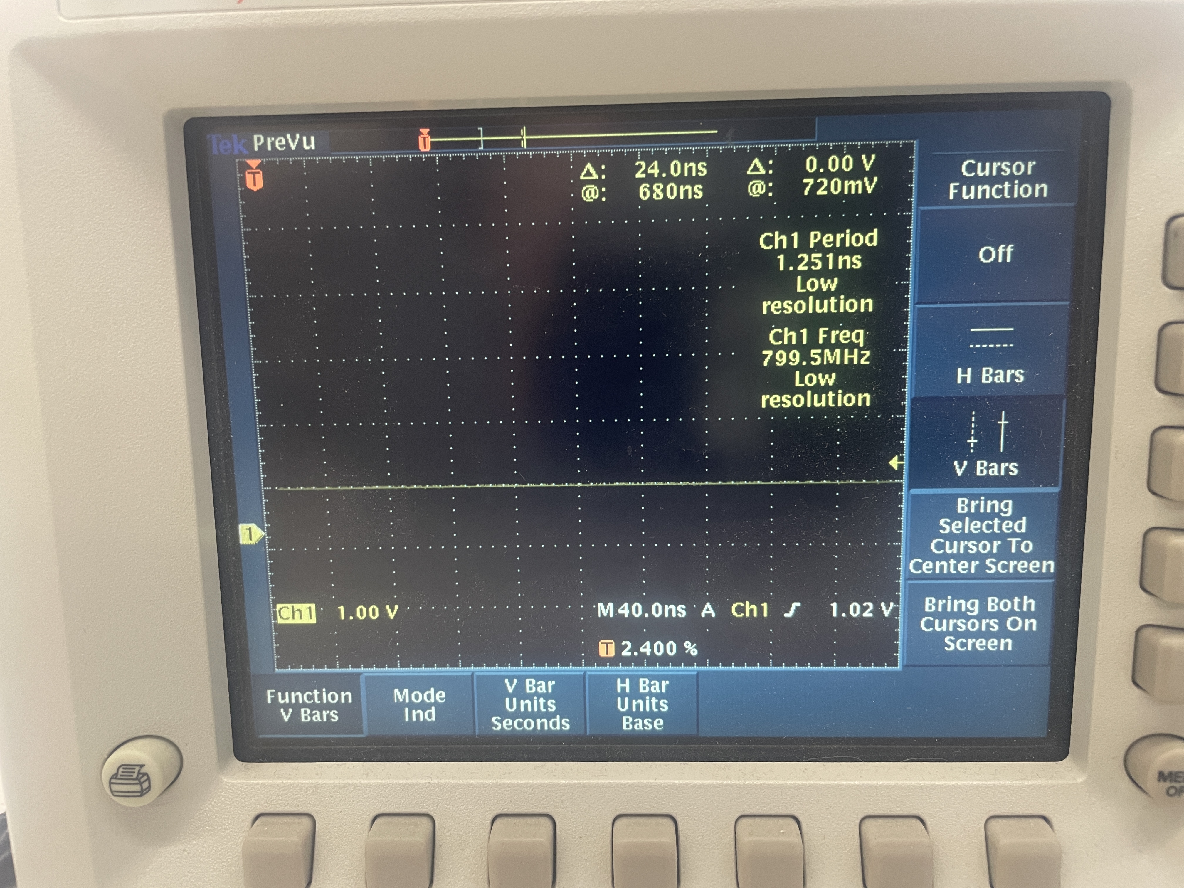
Oscilloscope
I plugged my pin into the digital pin of an LED, and I think my results simply showed a steady pattern--I didn't really see any square wave pattern. Not totally sure if this is what I was supposed to see, but I zoomed around a couple of times and stopped it, etc and couldn't really get anything else. There was nothing at all when the switch was off (as expected).