Part 1: Capacitive sensor
I wanted to use this week's assignment to begin testing out ideas for my final project. The main input in my final project is to detect whether pieces are on a light switch board. A stretch goal of mine was to see if each board place could detect whether or not the correct piece was in the spot--this week, I wanted to see if we could use capacitive sensors to detect this. (The answer was no, which we will see.)
My original idea for the capacitive sensor was to have it measure magnetic fields, as my plans for the inputs on my final project are to have them snap into place on the board using magnets. I spent a long time testing if the capacitive sensor could detect different magnets--my line of thinking was that stronger magnets should result in larger proxy capacitance values, as the distance between the plates should be stronger. It turns out that not only are the parallel capacitance sensors really fickle, but also constantly ripping magnets apart can drastically change readings between trials. Also, I didn't really know how to measure magnetic fields...
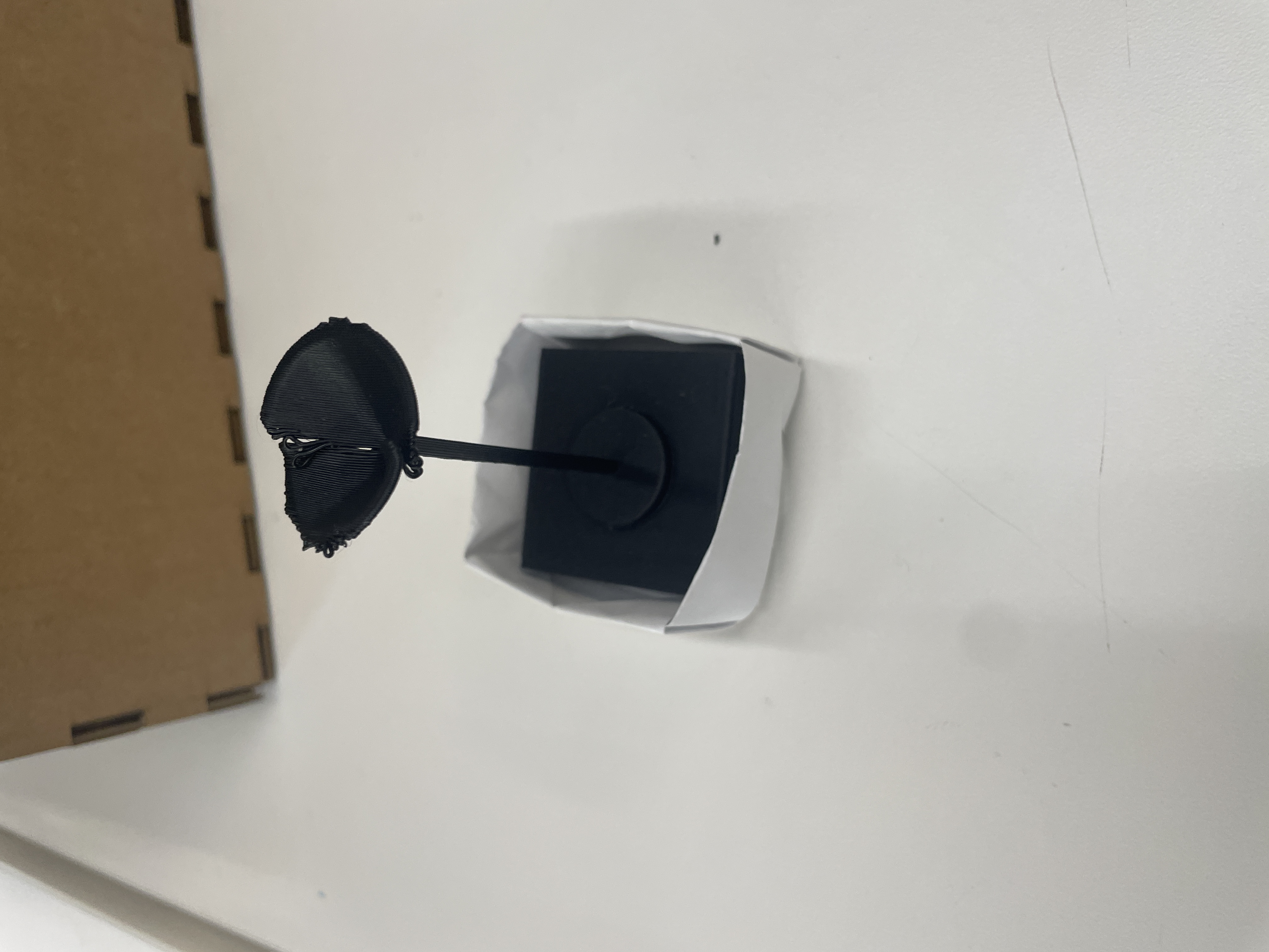
While playing around with the "ripping magnets apart" problem, I made a little origami box to control where the base plate and the piece plate would meet, and then tried to see if I could get semi-consistent readings. This didn't really work, so I switched to trying to get these plates to detect weight, which seemed simpler. This calibration ended up being much more successful, though there were still quite a few issues.
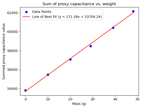
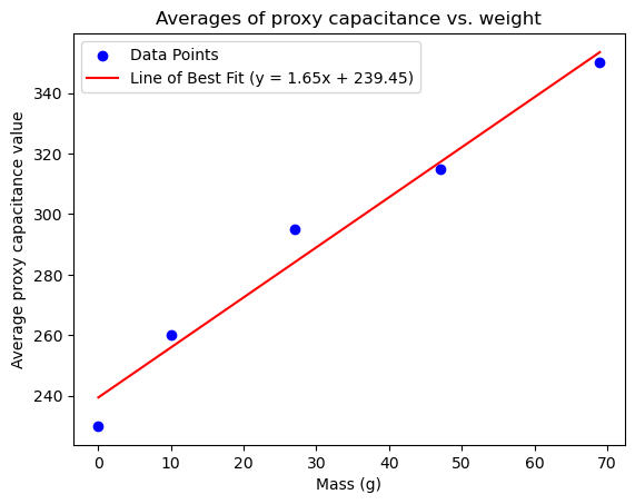
On calibration, the relationship actually looked very linear. However, when looking at the sensor values themselves, they looked like they fluctuated a lot. I therefore increased the number of samples taken to 1000, and to make the numbers less extreme, I took average readings. In any case, these relationships looked really linear.
Part 2: Circuitry & Code
This was the most painless part of the process, though I did rewrite my code halfway through. My first idea only had three different inputs and set red/blue/green values as true/false, then turned exactly one of the lights on depending on which light piece was detected. Halfway through, I realized I needed 4 different light settings, so I instead changed rgb values to be floats from 0 to 1, representing the ratio of total "light" that should be from that LED. Supposedly, this should control the actual color that we see (like orange is 50:21:6 for R:G:B). The maximum light value for each color is then modulated by this ratio, as well as an intensity value (from the phototransistor). Otherwise, I just zombied a lot of code together from lab and class.
#include <math.h>

const int analogCapacitorPin = A0;
const int txPin = D3;

const int photoresistorPin = A1;

const int redPin = D4;
const int bluePin = D6;
const int greenPin = D5;

int Vo;
float R1 = 10000;
float R2, T;
float A = 3.354e-03;
float B = 2.5698e-4;


class Capacitor{
  int currentState;
  int lastState = 0;

  public:
  // set up class
  Capacitor(int txPin){
    pinMode(txPin, OUTPUT);
  };

  long tx_rx() {  // Function to execute rx_tx algorithm and return a value
                // that depends on coupling of two electrodes.
                // Value returned is a long integer.
    int read_high;
    int read_low;
    int diff;
    long int sum;
    int N_samples = 1000;  // Number of samples to take.  Larger number slows it down, but reduces scatter.

    sum = 0;

    for (int i = 0; i < N_samples; i++) {
      digitalWrite(txPin, HIGH);          // Step the voltage high on conductor 1.
      read_high = analogRead(analogCapacitorPin);  // Measure response of conductor 2.
      delayMicroseconds(100);              // Delay to reach steady state.
      digitalWrite(txPin, LOW);           // Step the voltage to zero on conductor 1.
      read_low = analogRead(analogCapacitorPin);   // Measure response of conductor 2.
      diff = read_high - read_low;         // desired answer is the difference between high and low.
      sum += diff;                         // Sums up N_samples of these measurements.
    }
    return sum / N_samples;
  }
};

class Photoresistor {

  public:
  Photoresistor(int photoresistorPin) {
    pinMode(photoresistorPin, INPUT);
  };

  float getReading() {
    int rawLight = analogRead(photoresistorPin);
    return rawLight;
  }
};

class LED {
  int colorMax = 255;
  float red;
  float green;
  float blue;

public:
  LED(int redPin, int bluePin, int greenPin) {
      pinMode(redPin, OUTPUT);   // red
      pinMode(bluePin, OUTPUT);  // blue
      pinMode(greenPin, OUTPUT);  // green
      red = blue = green = 0.;
  };

  void off() {
    red = blue = green = 0;
    analogWrite(redPin, 0);
    analogWrite(greenPin, 0);
    analogWrite(bluePin, 0);
  }

  // floor lamp is red
  void lamp1() {
    red = 1.;
    green = 0.;
    blue = 0.;
  }

  // desk lamp is orange
  void lamp2() {
    red = 1.;
    green = .41;
    blue = .12;
  }

  // lightbulb is green
  void lamp3() {
    red = 0.;
    green = 1.;
    blue = 0.;
  }

  // nightstand lamp is purple
  void lamp4() {
    red = .63;
    green = 0.;
    blue = .94;
  }

  void changeIntensity(int intensity) {
    int ledPercent = map(intensity, 4095, 2800, 0, 100);
    int redVal = round(red * ((float) ledPercent/100) * colorMax);
    int greenVal = round(green * ((float) ledPercent/100) * colorMax);
    int blueVal = round(blue * ((float) ledPercent/100) * colorMax);

    analogWrite(redPin, redVal);
    analogWrite(greenPin, greenVal);
    analogWrite(bluePin, blueVal);
  }
};


Capacitor capacitor(txPin);
Photoresistor photoresistor(photoresistorPin);
LED led(redPin, bluePin, greenPin);
int baseCapacitance;


void setup() {
  Serial.begin(9600);                // start communication from arduino on this port
  led.off();
  baseCapacitance = capacitor.tx_rx();
}


void loop() {
  long capacitorVal = capacitor.tx_rx();
  float intensity = photoresistor.getReading();

  // base value: light off
  if (capacitorVal < baseCapacitance + 30) {
    led.off();
    // floor lamp, red
  } else if (capacitorVal < baseCapacitance + 30 + 35) {
    led.lamp1();
    // desk lamp, orange
  } else if (capacitorVal < baseCapacitance + 30 + 35 + 20) {
    led.lamp2();
    // lightbulb, green
  } else if (capacitorVal < baseCapacitance + 30 + 35 + 20 + 35) {
    led.lamp3();
    // nightstand lamp, purple
  } else  if (capacitorVal < baseCapacitance + 30 + 35 + 20 + 35 + 30) {
    led.lamp4();
  } else {
    led.off();
  }

  led.changeIntensity(intensity);
}
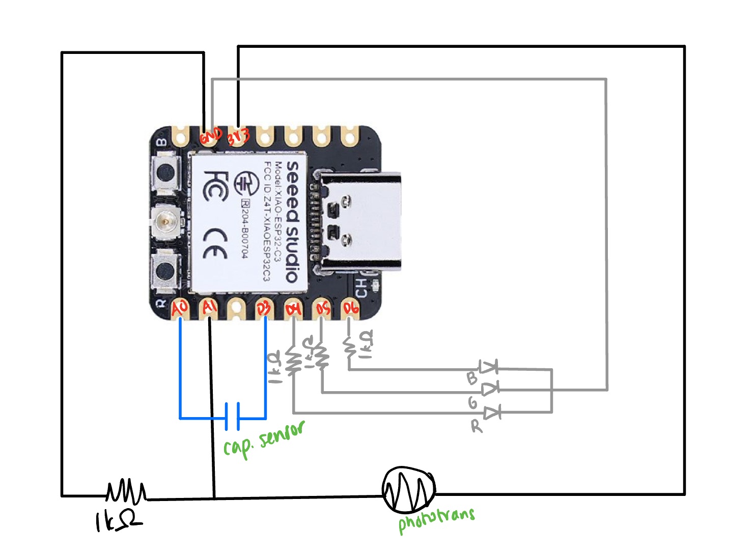
The circuitry was pretty much what was in the lecture notes.
Part 3: Minutae
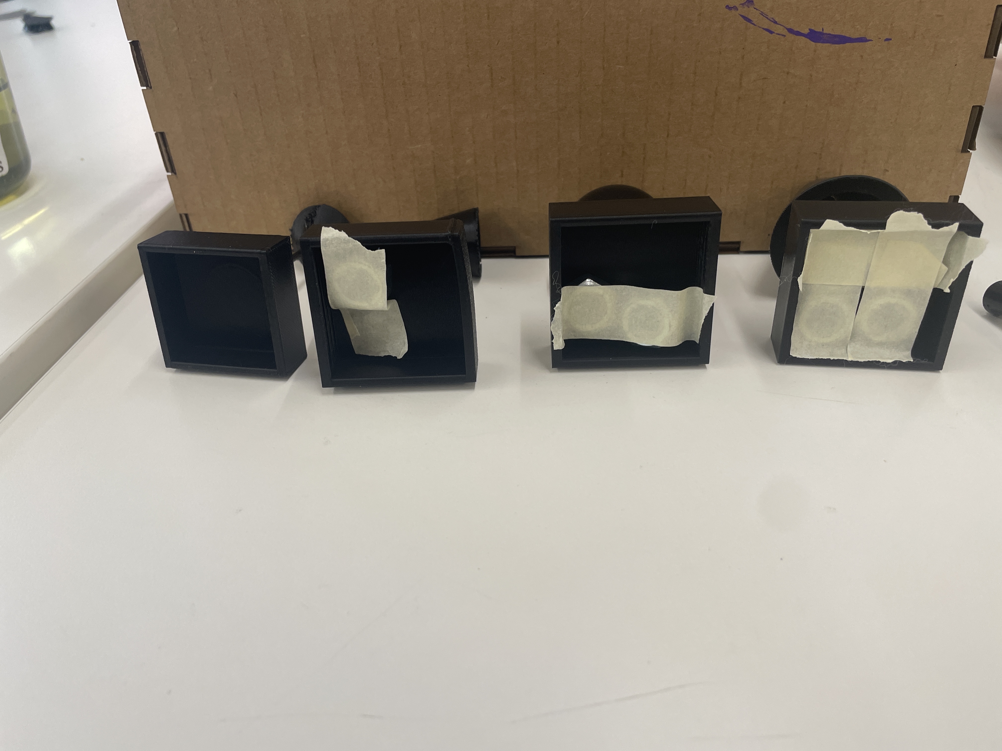
I then printed my 3D lamp pieces and tried to see if their intrinsic differences in weight would be good enough for the capacitive sensor to categorize them. This print was mostly a test run, as I scaled them down to be 4cm along each baselength, and I was mostly trying to see if they would turn out ok. Curiously, only the floor lamp turned out pretty poorly: I might try printing the top part as a separate piece and attaching it later (seen in the picture at the top).
It also turned out that the differences in weight for the lamps was not enough for the capacitive sensor to categorize. I thus taped some really big hex nuts to the bases of the lamps, until the final weights were (10g, 27g, 47g, 69g).
The last major issue (beyond huge fluctuations in capacitance generally) is that the "base" capacitance when nothing is on the sensor varies wildly between trials/how the sensor is initially set up. I tried to offset this by having the arduino take a base reading and then using the linear relationship seen in my calibration above to set the cutoffs for each classification, but this is still really fickle and not a great workaround. Also, if you touch the sensor in any way that shifts the plates (up/down or left/right), obviously the base value changes. I spent many many hours trying to figure out how to set cutoffs, since the numbers just kept changing between trials. I finally just eyeballed the changes in fluctuations between trials and landed on these cutoffs, but they are certainly not backed by hard data collection (which in retrospect may have been a good idea). I should find a better way to secure the plates, but I also can't figure out how to secure them because it would affect the virtual motion of the plates (affecting distance measured).
The last thing I should mention is the phototransistor, which I hooked up like in class. I made it so that in the dark, the LED would be brighter and when it's light out, the LED is basically off. I had to manually change the baseline to be 2800, as the PS70 shop is pretty bright.
Ultimately, unless I can figure out how to stabilize these capacitors, I think that voltage dividers might be a better idea for classifying which lamp is on a certain square. But this was still a good exercise, however frustrating it was.
Part 4: CNC Files
For these, I just outlined a shape of Taiwan and extruded a bunch of shapes. I'm not sure if the lines are too thin...