This week we had to program an arduino board to do something. I decided to continue iterating on my project from last week. Namely, I really wanted to redo the double helix so its pitch was tighter, and I also wanted to add more moving parts to it.
Part 1: Sculpture Fixes
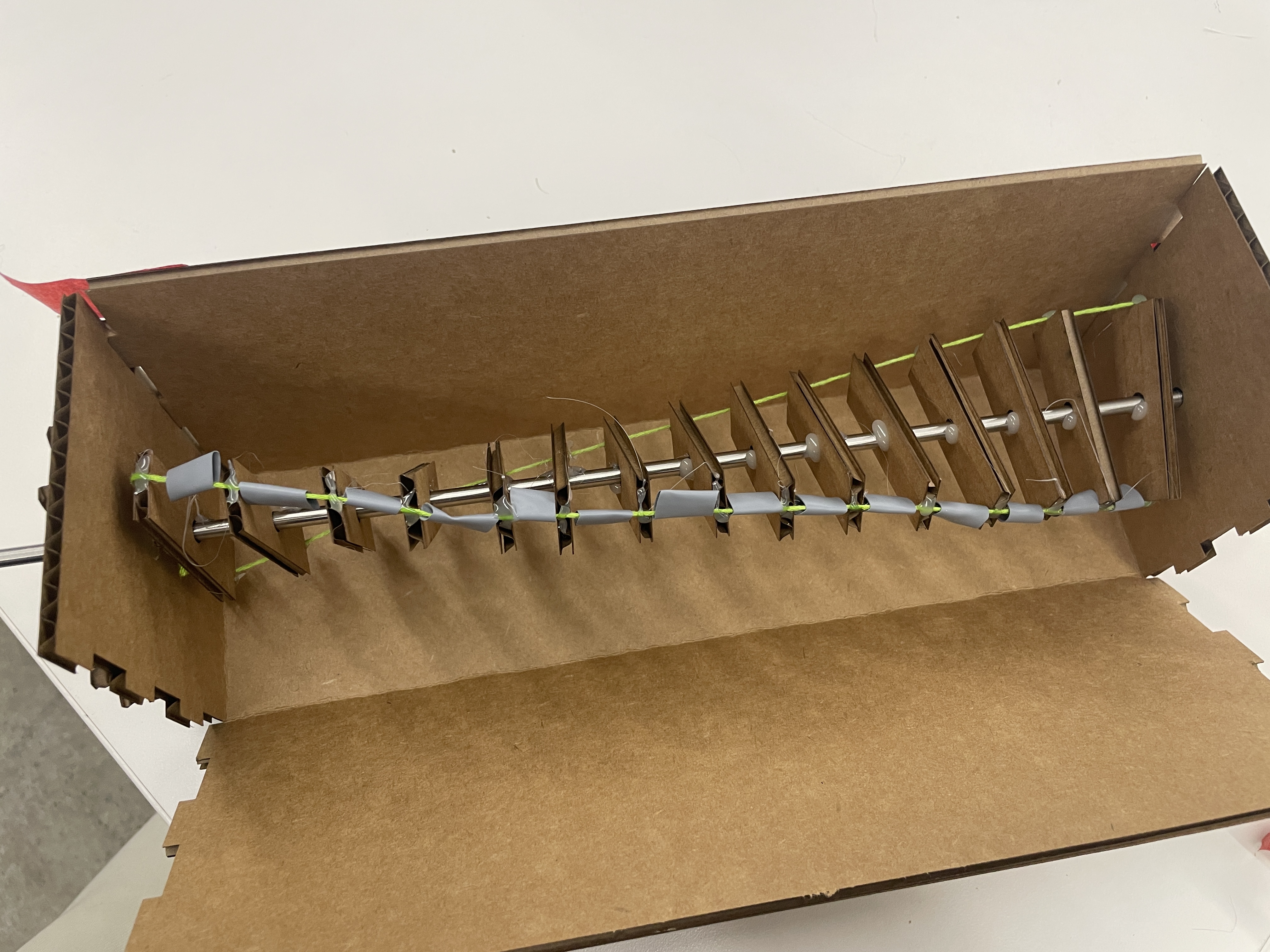
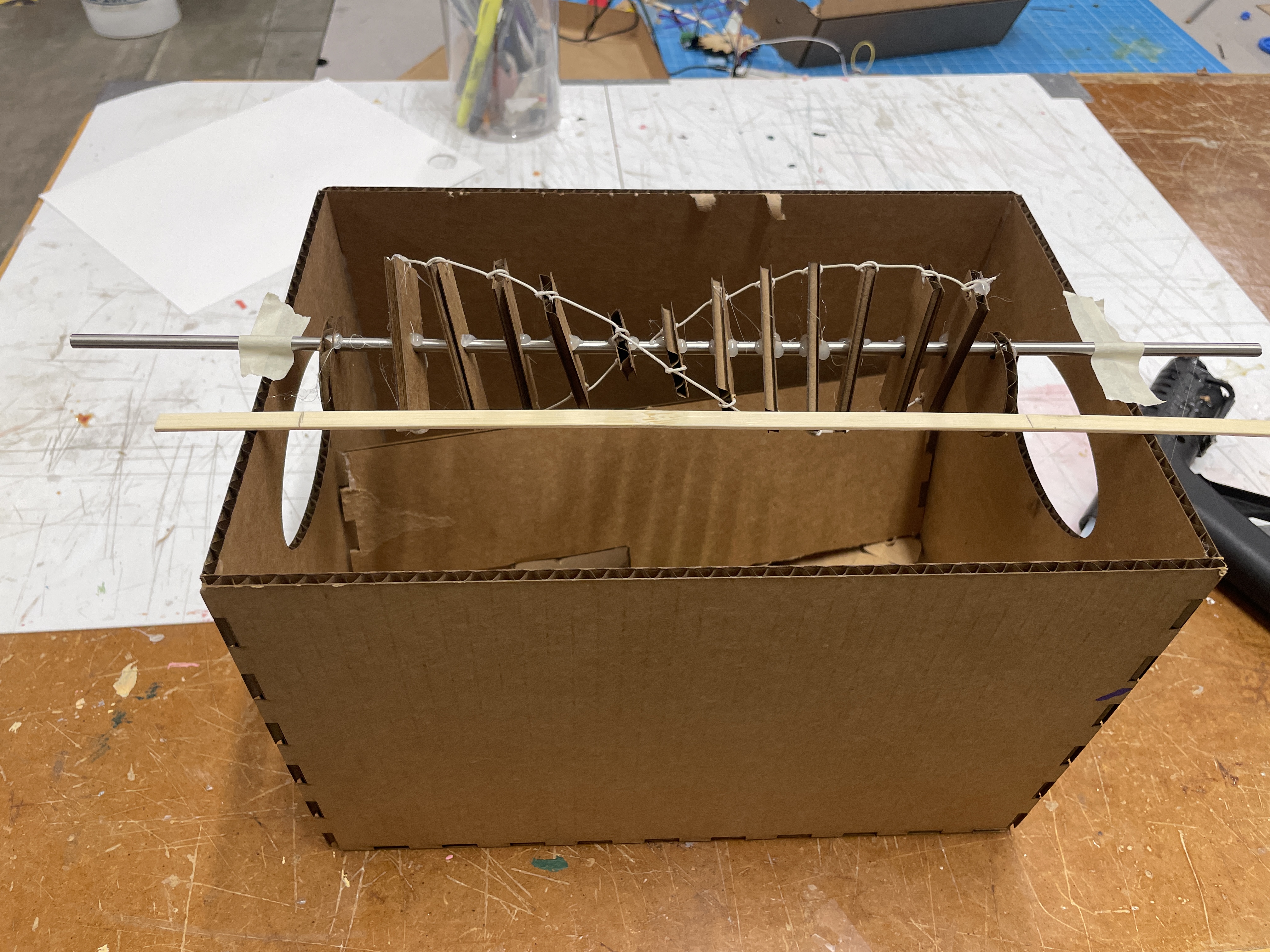
I started by fixing the double helix. To do this, I planned on using strings threaded through the DNA ladder layers to twist the helix, securing the shape with a jig, then hot glue-ing the shape onto the rod. I first re-printed the box and DNA ladder layers--the only difference was that the ladder layers had little points printed onto the sides so that I could thread strings through them (also, some small holes cut out on top to allow for the vertical movement in part 2). I then disassembled the sculpture to recover the center rod, threaded and knotted the ladder into place, and twisted the helix as tightly as possible. I was able to use the box from last week to secure the helix while I glued the helix in place. You can see the before and after below!
I also recut my gears out of wood because the cardboard sounds from my first iteration's gears were freaking me out.
Part 2: Sculpture Additions
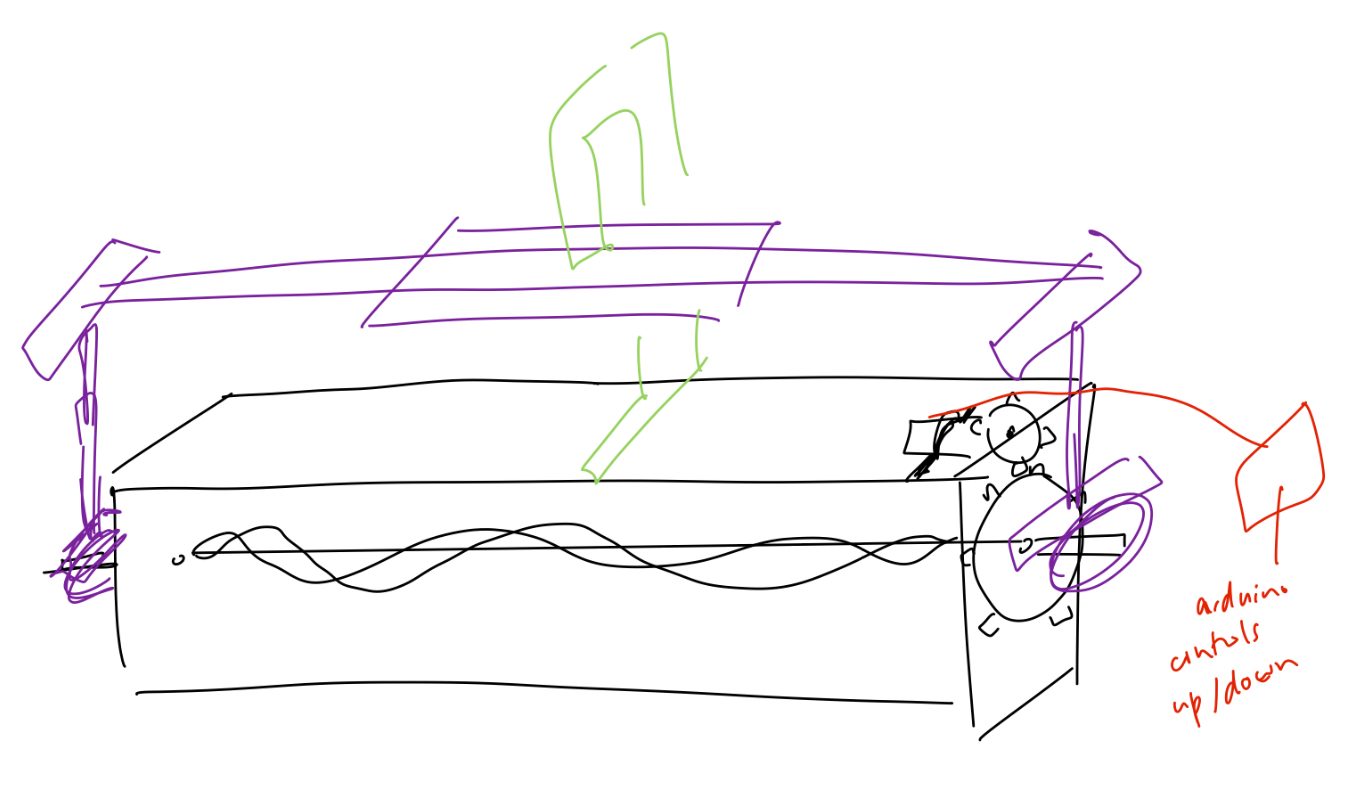
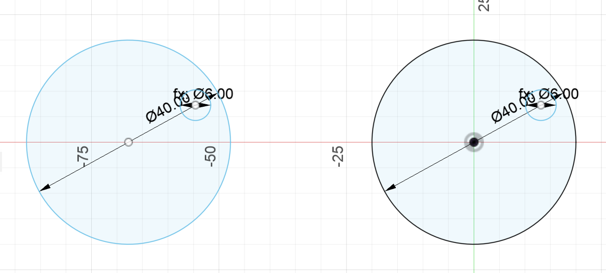
My original idea was to have my arduino control the direction in which the microscope platform moved, since I wanted to use a pulley. But this seemed a bit overkill, so I just focused on translating the rotational motion of the rod into a linear vertical motion. My idea was to use vertical motion platforms which would slide freely over wheels attached to the central rod. These platforms were just two pieces of cardboard (reusing the DNA ladders from last week's sculpture) connected to two thin straws. I also looked at a past project for inspiration, since originally I was trying to use an oval to generate the vertical motion (where the rod went through the center). This ended up making the motion really choppy, since the moving platform would get stuck on the long edge of the oval. I switched to just using a circle where the rod didn't go through the center, and this worked a bit better.
I made a lot of mistakes and miscalculations at this point, and I sunk many unhappy hours into trying to get this motion smoother and vertical. First, the original holes I laser cut for the vertical motion platforms were not in the right space, as they would have blocked the motor. I played around a lot with where to put the platforms so that they wouldn't collide with the sides of the box or the rungs of the DNA ladder. After I figured out the right spot, I drilled holes manually into the top of the box, but these holes were a lot less smooth than laser-cut holes. I thus had to duct-tape the sides of the holes so they wouldn't prevent the straws of the vertical platforms from sticking to the box.
My next problem was that since I was trying to prevent the straws from sticking to the box, I wasn't able to constrain the motion to be purely vertical. But then Jess walked past and and casually suggested I use slightly larger straws to constrain the motion, and this genuinely blew my mind. It also eliminated the need for rails on the vertical platforms where they moved over the wheels (which is something else that I played with while tinkering with my first iteration). I then hot-glued slightly larger straws into the drilled holes, but I had to do this a couple of times because the hot glue was really hot and melted the plastic--melted plastic usually shrinks and sadly also prevents the platforms from moving freely. After several tries, I was finally able to get the platforms to move up and down smoothly.
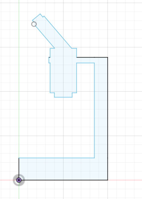
The last step was to just create the microscope image, so I threw together some shapes in Fusion and cut/paste it all together.
Part 3: Arduino
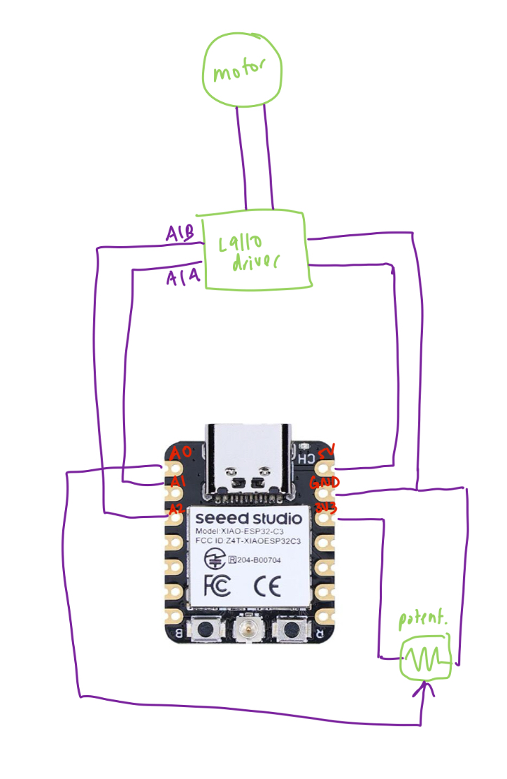
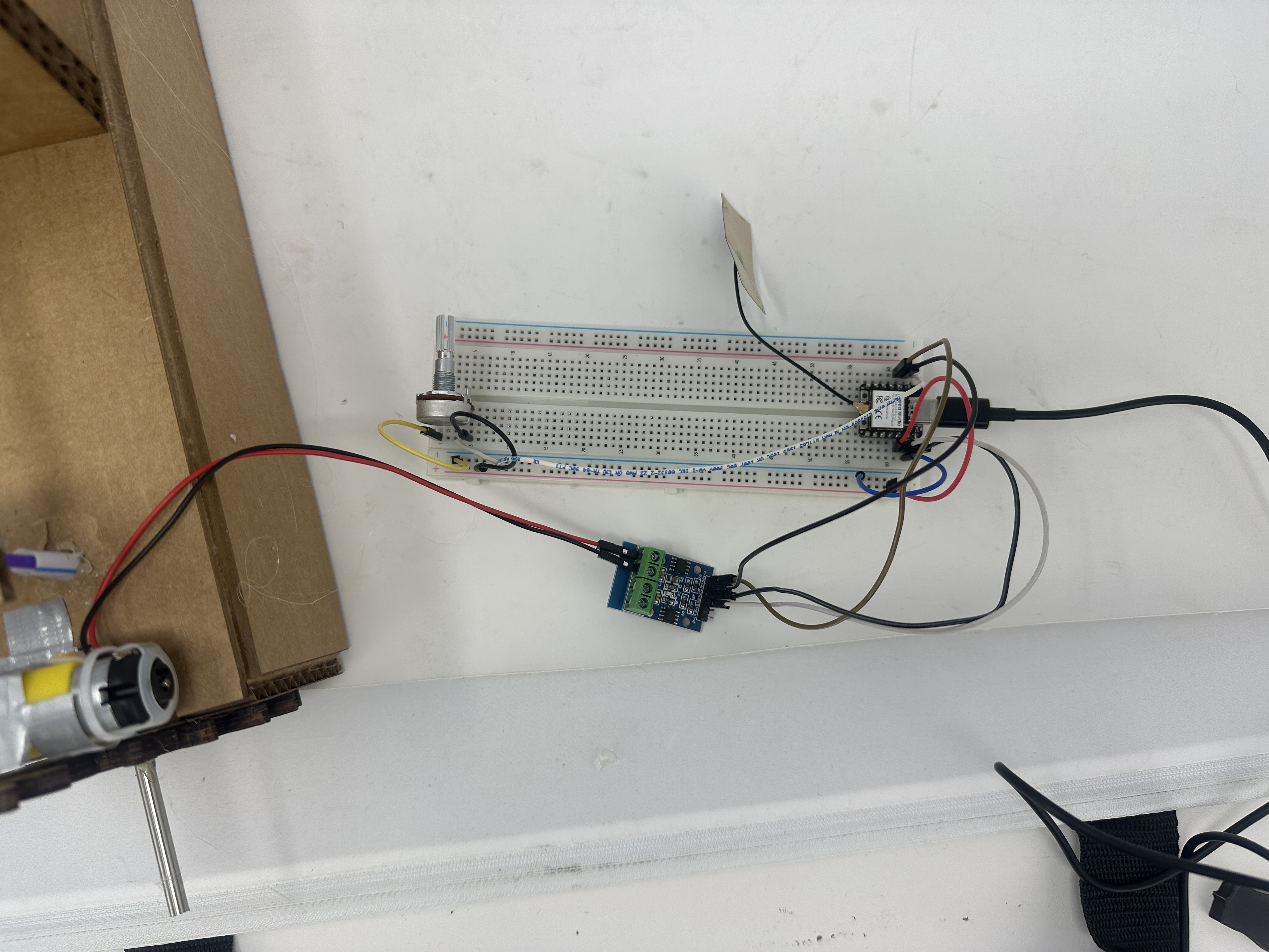
I then programmed my arduino to adjust the speed of the motor using a potentiometer. Most of this was explained in lecture, but I basically created circuits with the motor and potentiometer connected to pins in my XIAO board, then connected/translated between them with a map() in my code.
const int A1A = A1;
const int A1B = A2;
int potPin = A0;
int potVal;


void setup() {
    // Set motor pins as outputs
    pinMode(A1A, OUTPUT);
    pinMode(A1B, OUTPUT);
}

void loop() {
    // Read potentiometer value
    int potValue = analogRead(potPin);

    // map pot value to pwm
    int motorSpeed = map(potValue, 0, 1023, 0, 255);

    // motor speed (forward)
    analogWrite(A1A, motorSpeed);
    digitalWrite(A1B, LOW);

    delay(10); // small delay for stability (ChatGPT)
}
I didn't really understand the potentiometer/motor example in the lecture slides, so I figured I would just connect the potentiometer to an analog pin in one circuit, and have the basic motor circuit connected to separate pins. The arduino code could handle the rest (aka the communication, etc).
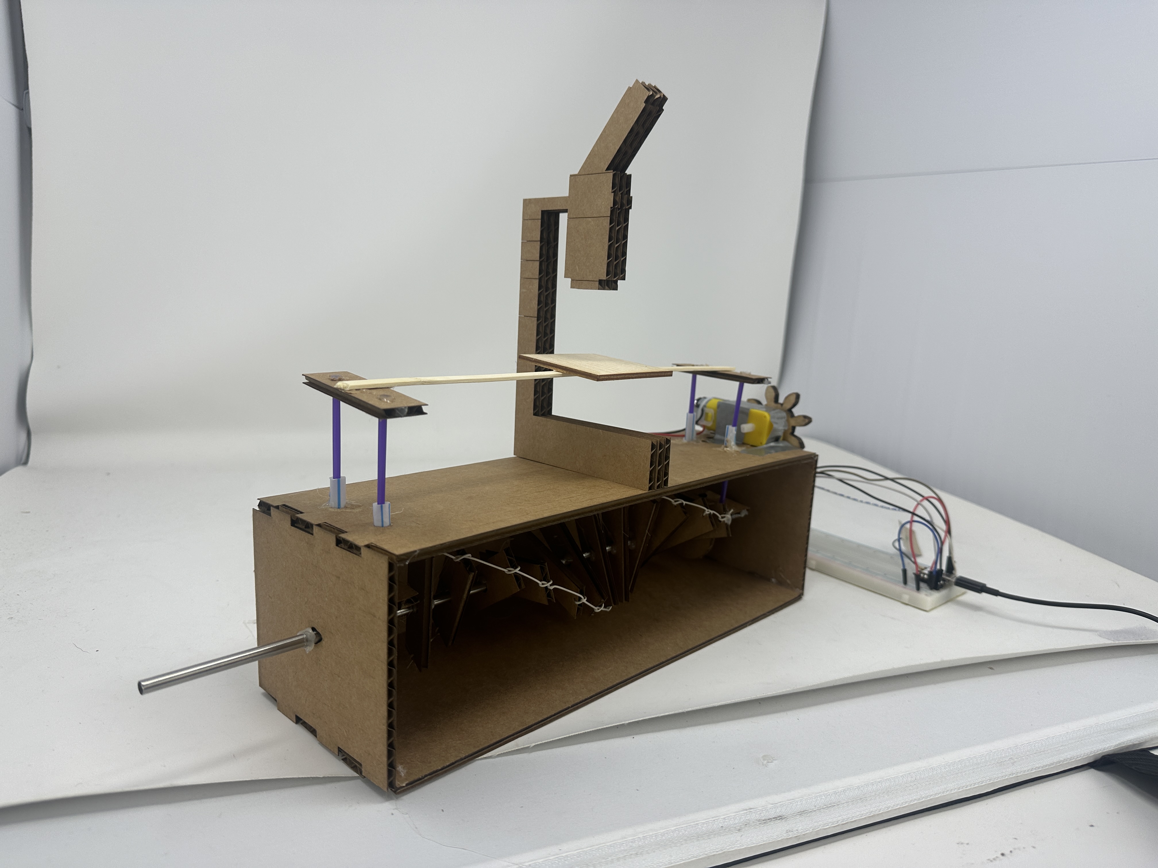
After hoooking the motor up to the rest of the helix sculpture, I was very pleased to see that the gears turned and things moved. Sometimes the motor gets stuck at certain potentiometer values, and I'm not sure what's going on there, but roughly as you turn the potentiometer, the motor spins faster/slower (depending on the direction).
Part 4: Final Sculpture